Concentration device capable of realizing automatic rotary defoaming and application thereof

A concentrating device, automatic rotation technology, applied in the direction of feeding device, chemical/physical/physical-chemical process, chemical instrument and method, etc., can solve problems affecting the normal operation of concentrating device, decomposition of effective components of compounds, collector ring water intake, etc. problems, to achieve the effect of increasing the unit capacity of the equipment, increasing the molecular motion, and increasing the molecular collision

Inactive Publication Date: 2020-06-09
GUANGXI FORESTRY RES INST
View PDF5 Cites 0 Cited by
  • Summary
  • Abstract
  • Description
  • Claims
  • Application Information

AI Technical Summary

Problems solved by technology

However, there are certain defects in the above-mentioned defoaming method. First, because the defoaming water pipe is located above the center of the concentration tank, that is, above the collector ring, it is easy to cause the collector ring to enter water when spraying water, causing a short-circuit shutdown; When the bubble ring collects too much foam at the center of the liquid surface, it is easy to cause the foam to enter the bearing of the concentrator, causing bearing damage and affecting the normal operation of the concentrator; and the concentrating process is prone to local overheating, resulting in the decomposition of the active ingredients of the compound Not enough

Method used


Image

  • Concentration device capable of realizing automatic rotary defoaming and application thereof

Examples


Embodiment 1

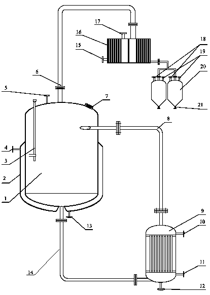
[0021] Such as figure 1 As shown, the automatic rotary defoaming and concentrating device of the present invention includes a reactor 1 and a heater 9; the top of the reactor 1 is connected to the top of the heater 9 through a material conduit A8, and the bottom of the reactor 1 is passed through a material The conduit B14 communicates with the bottom of the heater 9 to form a circulating heating system; the shell of the reaction kettle 1 is provided with a jacket 2, the upper end of the jacket 2 is provided with a steam inlet A4, and the upper end of the heater 9 is provided with a steam inlet B10, The bottom of the reactor 1 is provided with a coolant outlet A, and the bottom of the heater 9 is provided with a coolant outlet B13; the top of the reactor 1 is also provided with a material inlet 5, a thermometer 3 and a sight glass 7; The bottom of the heater 9 is provided with a discharge port A12; the top of the heater 9 is level with the bottom of the reaction kettle 1 . Th...


PUM


Abstract

The invention discloses a concentration device capable of realizing automatic rotary defoaming and application thereof. The concentration device capable of realizing automatic rotary defoaming comprises a reaction kettle and a heater, wherein the upper part of the reaction kettle is connected with the top of the heater through a material conduit A; the bottom of the reaction kettle communicates with the bottom of the heater through a material conduit B; a jacket is arranged outside a shell of the reaction kettle; a steam inlet A is formed in the upper end of the jacket; a steam inlet B is formed in the upper end of the heater; a cooling liquid outlet A is formed in the bottom of the reaction kettle, and a cooling liquid outlet B is formed in the bottom of the heater; a material inlet, a material outlet C and a thermometer are respectively arranged at the top of the reaction kettle; a discharge hole is formed in the bottom of the heater; the top end of the heater is flush with the bottom end of the reaction kettle; a material guide pipe C is connected with a condenser; and the bottom end of the condenser is connected with a solution collecting tank. According to the device, the heater is added according to a thermodynamic principle, so a cyclic heating system is formed between the reaction kettle and the heater, a heating system can be kept balanced, and local overheating is reduced to the greatest extent; and bubbles are broken through acceleration, so an automatic defoaming function is achieved.

Description

technical field [0001] The invention belongs to the technical field of chemical equipment, in particular to an automatic rotating defoaming and concentrating device and its application. Background technique [0002] The concentration process is a common production process in the production process of products in many industries such as chemical industry, food, and medicine. In the process of material concentration, due to the characteristics of the material, it is often encountered that the material liquid foams, and it is easy to form the phenomenon of material running, bumping, etc., resulting in an unstable state of the concentration process, and the concentration process cannot meet the production requirements. , Concentration equipment cannot operate stably, etc., which seriously affect the production efficiency of the concentration process. [0003] The current defoaming method often adds a defoaming agent in the concentration device, but in many evaporation and conce...

Claims


Application Information

Patent Timeline
Patent Type & Authority Applications(China)
IPC IPC(8): B01J19/00B01J4/00
CPCB01J4/001B01J4/008B01J19/0006B01J19/0013B01J19/002B01J2204/007B01J2219/00094B01J2219/00103B01J2219/0025
Inventor 陆顺忠关继华吴建文汤星月陆葆荣
Owner GUANGXI FORESTRY RES INST
Why Eureka
Try Eureka