A pin shaft milling machine

A technology of milling and pinning, applied in the field of profile processing, can solve the problems of high labor cost, low dimensional accuracy, and difficulty in effectively guaranteeing product quality.

Active Publication Date: 2021-07-06
HARBIN UNIV OF COMMERCE
View PDF7 Cites 0 Cited by
  • Summary
  • Abstract
  • Description
  • Claims
  • Application Information

AI Technical Summary

Problems solved by technology

[0002] In the production and processing of aluminum alloy window frames, door frames, etc., aluminum profiles are often used to make pins at hinges, such as figure 1 As shown, the aluminum profile is a combination of a cuboid and a cylinder. It is necessary to perform secondary processing on its length and shape according to the requirements. It is necessary to cut off the cylinders at both ends and keep the cuboid, and then obtain the following: Figure 13 The pin shaft structure shown, because of the special structure of the pin shaft, the existing pin shaft processing method is mainly manual milling, the use of mechanical equipment is relatively small, the efficiency is low, the labor intensity of the workers is high, and the labor cost is high. When observed with the naked eye, the dimensional accuracy of aluminum profiles after processing is low, and it is difficult to effectively guarantee product quality

Method used


Image

  • A pin shaft milling machine
  • A pin shaft milling machine
  • A pin shaft milling machine

Examples


Embodiment 1

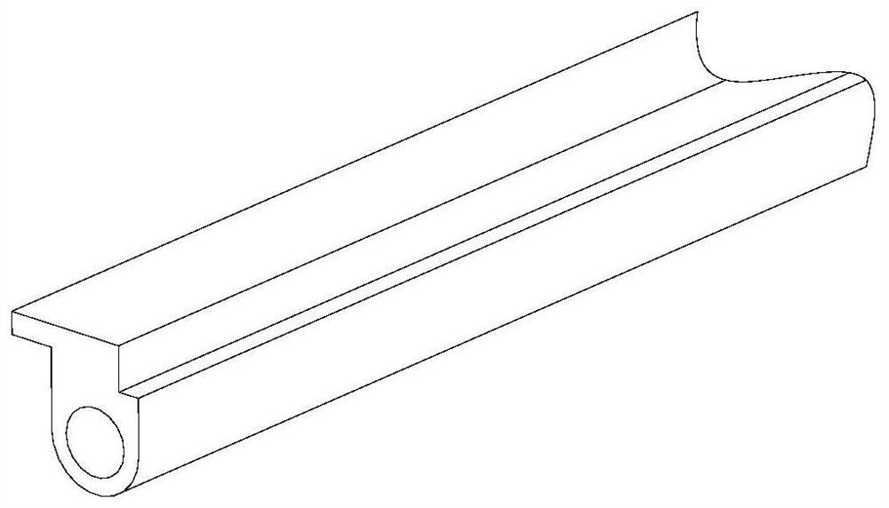
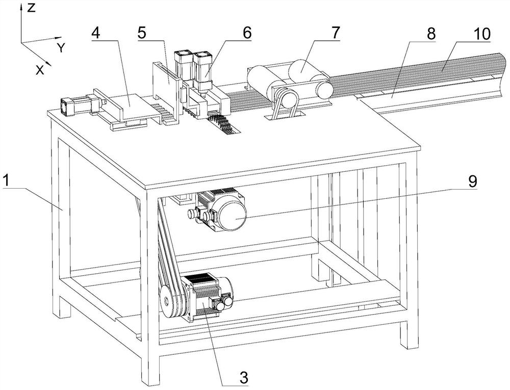
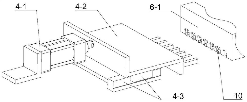
[0031] Such as figure 2 , a pin shaft milling machine, comprising a frame 1, a power unit 3 and a milling mechanism 9, the above frame 1 is a workbench, the power unit 3 is installed on the inner bottom of the frame 1, and the power unit 3 provides power for the milling mechanism 9, and this embodiment also includes a horizontal positioning mechanism 4, a vertical positioning mechanism 5, a pressing mechanism 6 and a feeding mechanism 7, and the horizontal positioning mechanism 4, the longitudinal positioning mechanism 5, and the pressing mechanism 6 and the feeding mechanism 7 are fixed on the worktable from left to right in sequence, and are located on a straight line. The milling mechanism 9 is located inside the frame 1 and below the pressing mechanism 6, and the corresponding part below the pressing mechanism 6 There is a milling notch on the working table, and the milling mechanism 9 moves in the milling notch, and the milling movement direction of the milling mechanism...


PUM


Abstract

The invention discloses a pin shaft milling machine, which comprises a frame, a power unit, a milling mechanism, a transverse positioning mechanism, a longitudinal positioning mechanism, a pressing mechanism and a feeding mechanism. The transverse positioning mechanism, the longitudinal positioning mechanism, the pressing mechanism The mechanism and the feeding mechanism are fixed on the worktable from left to right in sequence, and are located on a straight line. The milling mechanism is located inside the frame and below the pressing mechanism, and the corresponding working surface below the pressing mechanism is provided with a milling cut, the milling mechanism moves in the milling cut, the milling mechanism includes a saw blade set, the saw blade set includes a middle saw blade and two side saw blades, the middle saw blade and the two sides are coaxially installed together, The saw blades on both sides are located on both sides of the middle saw blade. The diameter of the middle saw blade is larger than that of the two side saw blades. The middle saw blade is used to cut the whole aluminum profile into multiple sections, and the two side saw blades are used to cut off the aluminum profile. cylinder on. The invention can process multiple aluminum profiles at one time, thereby improving the processing efficiency.

Description

technical field [0001] The invention relates to the field of profile processing, in particular to a pin shaft milling machine. Background technique [0002] In the production and processing of aluminum alloy window frames, door frames, etc., aluminum profiles are often used to make pins at hinges, such as figure 1 As shown, the aluminum profile is a combination of a cuboid and a cylinder. It is necessary to perform secondary processing on its length and shape according to the requirements. It is necessary to cut off the cylinders at both ends and keep the cuboid, and then obtain the following: Figure 13 The pin shaft structure shown, because of the special structure of the pin shaft, the existing pin shaft processing method is mainly manual milling, the use of mechanical equipment is relatively small, the efficiency is low, the labor intensity of the workers is high, and the labor cost is high. When observing with the naked eye, the dimensional accuracy of aluminum profile...

Claims


Application Information

Patent Timeline
Patent Type & Authority Patents(China)
IPC IPC(8): B23D45/06B23D45/10B23D47/04B23D47/08B23D47/12
CPCB23D45/06B23D45/10B23D47/04B23D47/042B23D47/08B23D47/12
Inventor 晏祖根
Owner HARBIN UNIV OF COMMERCE
Why Eureka
Try Eureka