Thin-film device

A thin-film device and component technology, applied in chemical instruments and methods, layered products, glass/slag layered products, etc., can solve the problems of reduced transparency, increased film manufacturing cost, low resistance, etc., and achieve high light transmittance , Improve stability, low resistance effect

Pending Publication Date: 2020-06-09
四川猛犸半导体科技有限公司
View PDF0 Cites 0 Cited by
  • Summary
  • Abstract
  • Description
  • Claims
  • Application Information

AI Technical Summary

Problems solved by technology

In many cases, lowering the resistance by increasing the dopant of the transparent conductive oxide film leads to an undesired decrease in transparency, and at the same time, some properties of the transparent conductive oxide film will be degraded after high temperature heat treatment
In addition, in order to further reduce the resistance of the transparent conductive oxide film, a thicker film layer is required, which will lead to a decrease in the transmittance of the film layer, an increase in the stress of the film layer, and an increase in the instability of the film layer, which also increases The manufacturing cost of the film layer
[0004] Thin-film devices used in applications such as solar cells, construction, and automobiles need to undergo high-temperature heat treatment during the preparation process. Therefore, the thin-film devices are required to withstand high-temperature heat treatment, and at the same time have high visible light transmittance, low resistance, Good mechanical resistance and high stability, etc., but the existing thin film devices cannot meet this requirement, it is necessary to improve it

Method used


Image

  • Thin-film device
  • Thin-film device
  • Thin-film device

Examples


Embodiment 1

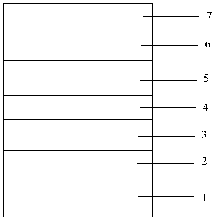
[0049] On the glass substrate 2.0C (substrate 1) is sequentially plated Si with a thickness of 38nm 3 N 4 Film layer; ZnO with a thickness of 8nm 2 Film layer is as dielectric film layer 2; Thickness is the silver film layer 3 of 12nm; Thickness is the GaMg interface film layer 4 of 0.05nm, wherein the content of Ga is 66at%; Thickness is the NiCr film layer (sacrifice film layer 5) of 2nm; ZnSnO with a thickness of 23nm 2 layer (top dielectric layer 6); Si with a thickness of 15nm 3 N 4 The film layer is used as the protective film layer 8 to obtain a heat-treatable coated glass, that is, a thin-film device, with a structure such as figure 1 shown.

[0050] Optical performance test:

[0051] Before heat treatment, the visible light transmittance of a single piece of coated glass is 83.1%; after heat treatment at 580°C for 10 minutes, the visible light transmittance of a single piece of coated glass is 84.3%, and the square resistance is 4.1Ω / □; then washing, assembling,...

Embodiment 2

[0055] On the glass substrate 2.0C (substrate 1), sequentially plate Si with a thickness of 35nm 3 N 4 Film layer; ZnO with a thickness of 10nm 2 Film layer is as dielectric film layer 2; Thickness is the silver film layer 3 of 12nm; Thickness is the GaMg interface film layer 4 of 0.5nm, wherein the content of Ga is 45at%; Thickness is the NiCr film layer (sacrifice film layer 5) of 2nm; ZnSnO with a thickness of 25nm 2 layer (top dielectric layer 6); Si with a thickness of 13nm 3 N 4 The film layer is used as the protective film layer 8 to obtain a heat-treatable coated glass, that is, a thin-film device, with a structure such as figure 1 shown.

[0056] Optical performance test:

[0057] Before heat treatment, the visible light transmittance of a single piece of coated glass is 82.8%; after heat treatment at 580°C for 10 minutes, the visible light transmittance of a single piece of coated glass is 84.1%, and the square resistance is 4.3Ω / □; then washing, assembling, et...

Embodiment 3

[0061] On the glass substrate 2.0C (substrate), sequentially plate Si with a thickness of 30nm 3 N 4 Film layer; ZnO with a thickness of 9nm 2 The film layer is used as a dielectric film layer; a GaMg interface film layer with a thickness of 1nm, wherein the Ga content is 66at%; a silver film layer with a thickness of 12nm; a NiCr film layer (sacrifice film layer) with a thickness of 2nm; a ZnSnO film layer with a thickness of 28nm 2 layer (top dielectric layer); Si with a thickness of 10nm 3 N 4 The film layer is used as a protective film layer to obtain heat-treatable coated glass, that is, a thin-film device.

[0062] Optical performance test:

[0063] Before heat treatment, the visible light transmittance of a single piece of coated glass is 82.1%; after heat treatment at 580°C for 10 minutes, the visible light transmittance of a single piece of coated glass is 83.3%, and the square resistance is 4.0Ω / □; then washing, assembling, etc. The visible light transmittance o...


PUM

PropertyMeasurementUnit
thicknessaaaaaaaaaa
thicknessaaaaaaaaaa
thicknessaaaaaaaaaa

Abstract

The invention discloses a thin-film device. The thin-film device comprises a substrate, a film layer assembly, a top dielectric film layer and a protective film layer which are stacked in sequence, wherein the film layer assembly comprises a dielectric film layer, a silver film layer and a sacrificial film layer which are sequentially stacked outwards along the substrate, or the film layer assembly comprises the dielectric film layer, the sacrificial film layer and the silver film layer which are sequentially stacked outwards along the substrate; the film assembly further comprises a GaMg interface film layer; and the GaMg interface film layer is arranged between the silver film layer and the sacrificial film layer and / or between the silver film layer and the dielectric film layer, and thecontent of Ga in the GaMg interface film layer is smaller than 67 at%. According to the invention, the stability of a film system in high-temperature heat treatment can be improved, the chemical stability and the mechanical properties of the thin-film device can be improved, and the thin-film device has high visible light transmittance and low resistance.

Description

technical field [0001] The invention belongs to the technical field of thin film devices, and in particular relates to a thin film device capable of high temperature heat treatment. Background technique [0002] Ordinary glass has no heat insulation function. With the enhancement of people's awareness of energy saving, many buildings or cars have now used coated glass (thin film device). Increased comfort in the car. [0003] Solar cells are photovoltaic elements used to directly generate electricity from sunlight. Due to the increasing demand for clean energy, the manufacturing of solar cells has expanded significantly in recent years and continues to expand. Transparent conductive oxide films are widely used in solar cells due to their versatility as transparent coatings and electrodes. In many cases, reducing electrical resistance by increasing the dopant of the transparent conductive oxide film leads to an undesired decrease in transparency, and at the same time, some...

Claims


Application Information

Patent Timeline
Patent Type & Authority Applications(China)
IPC IPC(8): C03C17/36C03C27/12B32B17/10
CPCB32B17/10036B32B2250/03B32B2250/40C03C17/3618C03C17/3626C03C17/3639C03C17/3644C03C17/3649C03C17/3652C03C27/10
Inventor 不公告发明人
Owner 四川猛犸半导体科技有限公司
Why Eureka
Try Eureka