Continuous beam bridge and method for determining inhaul cable sectional area and elastomer rigidity thereof

An elastic body, beam bridge technology, applied in bridges, bridge construction, bridge parts, etc., can solve the problems of easy damage, large bending moment at the bottom of fixed piers, damage to the whole bridge, etc., and achieve economical and low-cost solutions. Effect

Active Publication Date: 2020-06-09
SOUTHWEST JIAOTONG UNIV +2
View PDF7 Cites 3 Cited by
  • Summary
  • Abstract
  • Description
  • Claims
  • Application Information

AI Technical Summary

Problems solved by technology

[0003] However, under the forward earthquake excitation, the horizontal inertia force generated by the continuous girder is almost entirely borne by the fixed pier, resulting in excessive bending moment at the bottom of the fixed pier, which is very prone to damage
In addition, due to the different stiffness of the piers, the assigned seismic bending moments are also different. It is easy to cause the pier with excessive bending to fail first, while the rest of the piers are still intact. The seismic performance of each pier cannot be fully utilized, resulting in the destruction of one pier. bridge disabled

Method used


Image

  • Continuous beam bridge and method for determining inhaul cable sectional area and elastomer rigidity thereof
  • Continuous beam bridge and method for determining inhaul cable sectional area and elastomer rigidity thereof
  • Continuous beam bridge and method for determining inhaul cable sectional area and elastomer rigidity thereof

Examples


Embodiment Construction

[0058] The specific embodiments of the present invention will be described in detail below in conjunction with the accompanying drawings, so that those skilled in the art can understand the present invention. However, it should be clear that the embodiments described below are only some, not all, embodiments of the present invention. Without departing from the spirit and scope of the present invention defined and determined by the appended claims, all other embodiments obtained by those skilled in the art without any creative effort shall fall within the protection scope of the present invention.

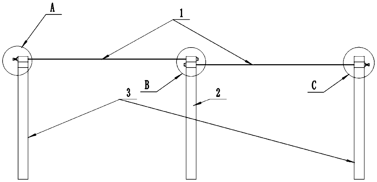
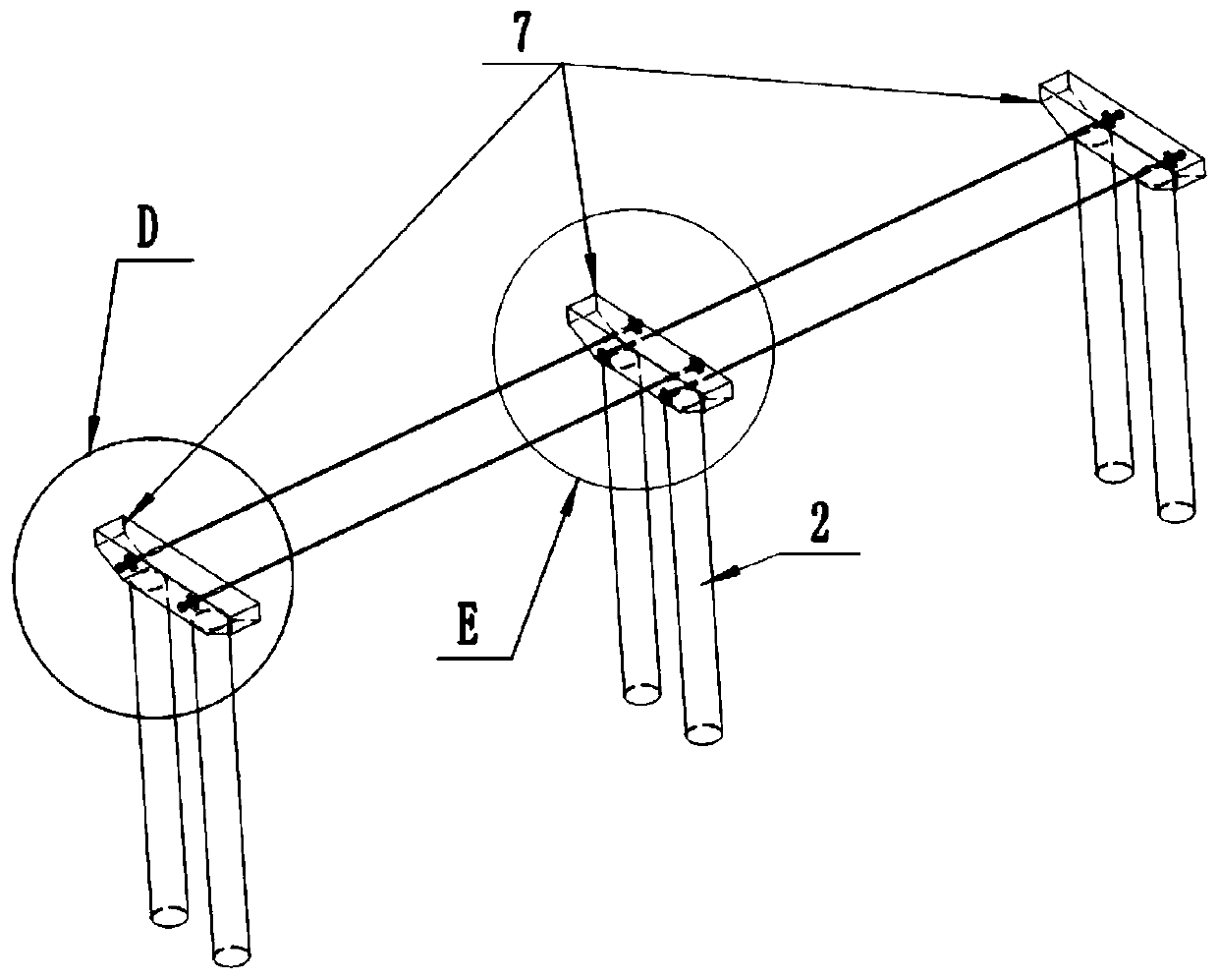
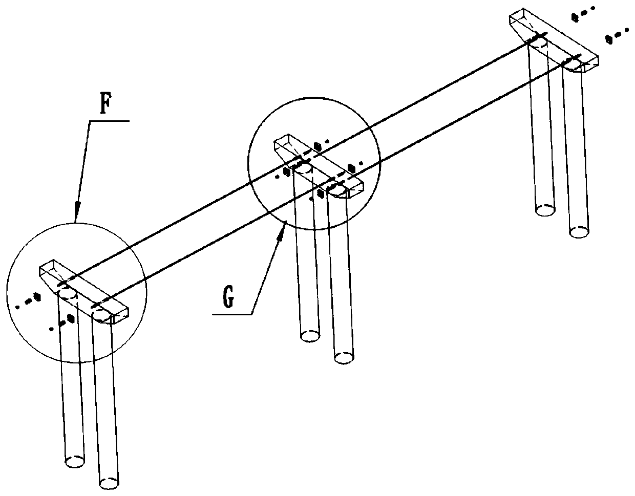
[0059] like Figure 1 to Figure 3 As shown, the continuous girder bridge includes a connecting cable device, a continuous main girder, piers and a plurality of pier cover girders 7 , and the piers include a fixed pier 2 in the middle and a plurality of non-fixed piers 3 on both sides of the fixed pier 2 . like Figure 4 and Figure 5 As shown, the pier cover beam 7 is provided wi...


PUM


Abstract

The invention discloses a continuous beam bridge and a method for determining an inhaul cable sectional area and elastomer rigidity thereof, and belongs to the field of civil engineering. Symmetricalthrough hole sets are formed in pier cap beams of the continuous beam bridge, each through hole set comprises two through holes, and casing pipes are installed in the through holes; a cable connectingdevice comprises inhaul cables which penetrate through the casing pipes on the adjacent pier cap beams respectively, and the inhaul cables are parallel to a continuous main beam; the pier top centersof fixed piers serves as original points, first pressing blocks and first anchorage devices are arranged at the ends, close to the original points, of the inhaul cables, and second pressing blocks, elastomers and second anchorage devices are sequentially arranged at the ends, away from the original points, of the inhaul cables, and the first pressing blocks and the second pressing blocks are closer to the centers of the inhaul cables than the first anchorage devices and the second anchorage devices respectively. According to the continuous beam bridge, under the earthquake excitation effect in the axial direction of the bridge, non-fixed piers cooperate with the fixed piers to share earthquake loads together, the destruction risk of the fixed piers of the continuous beam bridge is reduced, meanwhile, the bending moment distribution of the piers is basically uniform, and the anti-seismic properties of the piers are brought into play, therefore the anti-seismic properties of the continuous beam bridge are improved.

Description

technical field [0001] The invention relates to the field of civil engineering, in particular to a continuous girder bridge and a method for determining the cross-sectional area of ​​its stay cables and the stiffness of an elastic body. Background technique [0002] The continuous girder bridge generally includes the upper continuous main girder, the lower pier and the pier cover girder on the pier. The continuous main girder and the pier cover girder are connected by fixed bearings or sliding bearings. Both fixed and sliding bearings are used to constrain the horizontal movement of the continuous girder. When the continuous girder and the pier cover girder are connected by a fixed support, the corresponding pier is called a fixed pier; when the continuous girder and the pier cover girder are connected by a sliding support, the continuous girder can correspond to the pier The horizontal movement of the cap beam corresponds to the bridge piers called non-fixed piers. Usuall...

Claims


Application Information

Patent Timeline
Patent Type & Authority Applications(China)
IPC IPC(8): E01D1/00E01D2/00E01D19/00G06F30/13G06F30/20G06F119/14
CPCE01D1/00E01D2/00E01D19/00
Inventor 赵灿晖陈良江陈克坚孙宗磊戴胜勇钟亚伟邓开来闫桂豪
Owner SOUTHWEST JIAOTONG UNIV
Why Eureka
Try Eureka