Eureka AIR delivers breakthrough ideas for toughest innovation challenges, trusted by R&D personnel around the world.

Turbine blade vibration test tool and turbine blade clamping method

A technology for turbine blade and vibration testing, applied in vibration testing, measuring devices, testing of machine/structural components, etc., can solve the problems of weak clamping rigidity, difficult vibration excitation, poor consistency, etc., to achieve reliable connection, simple structure, Easy installation and removal

Inactive Publication Date: 2020-06-09
AECC AVIATION POWER CO LTD
View PDF12 Cites 5 Cited by
  • Summary
  • Abstract
  • Description
  • Claims
  • Application Information

AI Technical Summary

Problems solved by technology

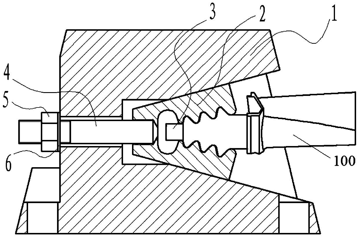
[0003] The invention provides a turbine blade vibration test tool and a turbine blade clamping method, which effectively solves the problems of weak clamping rigidity, poor consistency, and difficulty in excitation of high-pressure turbine blades of aero-engines

Method used


Image

  • Turbine blade vibration test tool and turbine blade clamping method
  • Turbine blade vibration test tool and turbine blade clamping method
  • Turbine blade vibration test tool and turbine blade clamping method

Examples


Embodiment Construction

[0034] In order to make the purpose and technical solution of the present invention clearer and easier to understand. The following describes the present invention in further detail with reference to the accompanying drawings and embodiments. The specific embodiments described here are only used to explain the present invention, not to limit the present invention.

[0035] In the description of the present invention, it should be understood that the terms "center", "longitudinal", "transverse", "upper", "lower", "front", "rear", "left", "right", " The orientation or positional relationship indicated by "vertical", "horizontal", "top", "bottom", "inner", "outer" etc. is based on the orientation or positional relationship shown in the drawings, and is only for the convenience of describing the present invention and The description is simplified, rather than indicating or implying that the pointed device or element must have a specific orientation, be constructed and operated in a s...


PUM


Abstract

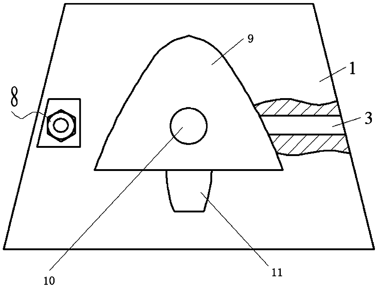
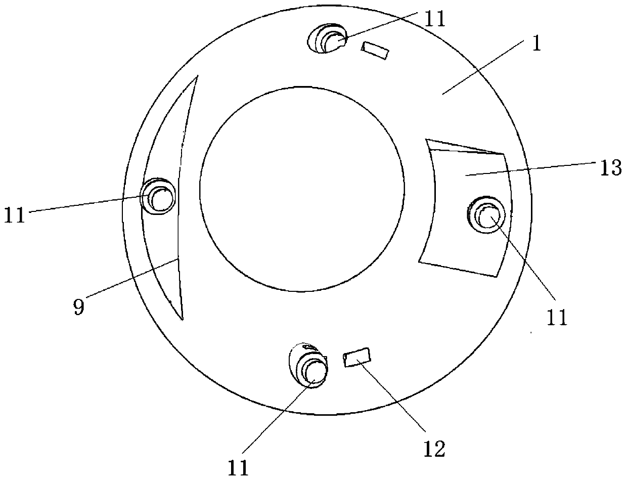
The invention discloses a turbine blade vibration test tool and a turbine blade clamping method, the vibration test tool comprises a main body, the main body is internally provided with an opening alignment chute inner cavity and a force application step hole, the included angle of the opening alignment chute inner cavity is the same as the included angle of blade tenon teeth, and the opening alignment chute inner cavity is used for placing a clamping block; the clamping block is provided with a clamping mortise and a large arc transition hollow elastic section, one end of the clamping block is provided with a threaded hole communicated with the hollow elastic section, and the threaded hole is used for installing a stress application screw. The other end of the connecting rod is connectedwith the nut; the stop block tightly abuts against the tenon bottom of the blade under the action of the adjusting bolt. The stress application screw penetrates through a stress application stepped hole in the main body and extends into the threaded hole of the clamping block, the stop block penetrates through the main body and the clamping block, and an adjusting bolt used for adjusting the position of the stop block is installed on the main body. According to the structure, the blade tenon is fixedly held through the combined action of pressing and jacking, so that the attachment area of thetenon tooth surface of the blade and a tool mortise is large, the contact is uniform, the fixedly holding rigidity is high, and the consistency is good.

Description

Technical field [0001] The invention belongs to the technical field of structural component vibration testing, and in particular relates to a turbine blade vibration testing tool and a turbine blade clamping method. Background technique [0002] Before the installation of aero-engine turbine blades, frequency measurement and sampling fatigue inspection tests are required. During the test, the blade tenon and the blade cantilever are required to ensure that the blade has good holding rigidity and clamping consistency. At present, two ways of pressing and tightening are used to achieve the holding of the blade tenon. The pressing method is composed of a door-shaped box and a clamp-shaped elastic pressing block structure. The door-shaped box is composed of a steel beam and two vertical It is composed of supporting plates. The structure has weak rigidity, heavy weight, low first-order natural frequency, and is easy to couple and vibrate with the blade; after the clamp-shaped elastic ...

Claims


Application Information

Patent Timeline
IPC IPC(8): G01M7/02
CPCG01M7/027
Inventor 杜文奎闫志祥张培健李季张振宇刘京春阎庆安李鹏
Owner AECC AVIATION POWER CO LTD
Why Eureka
Eureka Blog
Learn More