Optical fiber connector and tail wiring assembly thereof
A technology for optical fiber connectors and wiring components, applied in optical components, light guides, optics, etc., can solve the problems of scratch damage, low reliability and pass rate, etc., to ensure safety, improve protection strength, and simplify the overall structure. Effect
- Summary
- Abstract
- Description
- Claims
- Application Information
AI Technical Summary
Problems solved by technology
Method used
Image

Examples
Embodiment 1
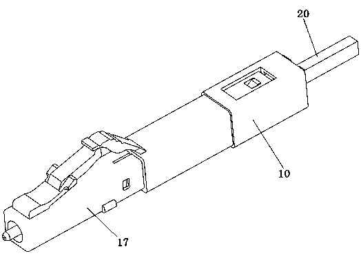
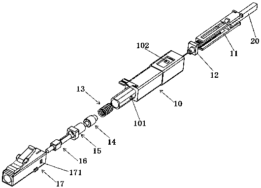
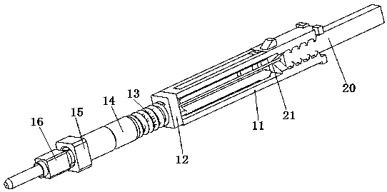
[0092] Embodiment 1 of the optical fiber connector in the present invention: the optical fiber connector in this embodiment is used to connect LC-type optical fibers, and can meet the requirement of fast on-site wiring of LC-type optical fibers. Such as figure 1 and figure 2 As shown, the optical fiber connector mainly includes a front housing 17, a ferrule assembly and a tail wiring assembly, and the tail wiring assembly includes a main housing 10, a fiber protection sliding sleeve 12 and an optical cable fixing member 11, which constitute the components of the optical fiber connector. There are many, so the structure of each part of the fiber optic connector is now explained.
[0093] The main housing 10 in the tail wiring assembly is installed on the rear end of the front housing 17 when assembling the optical fiber connector, and is assembled with the front housing 17 to form a shell, and the two sides of the main housing 10 are provided with triangular main housings bu...
Embodiment 2
[0112]Embodiment 2 of the optical fiber connector in the present invention: the difference from the above embodiments is that in this embodiment, the fiber protection sliding sleeve is inserted into the optical cable fixing part, and the wall surface that cooperates with the fiber protection sliding sleeve in the optical cable fixing part The rubber strip or frosted surface is set on the top, and the friction between the fiber protection sliding sleeve and the rubber strip or the frosted surface is relatively large, which can realize the sliding resistance cooperation between the fiber protection sliding sleeve and the optical cable fixing piece in the direction of the insertion sleeve, and make the optical fiber from the When stretching out from the fiber protection sliding sleeve, the operator needs to apply force to overcome the frictional force between the fiber protection sliding sleeve and the optical cable fixing member, so that the fiber protecting sliding sleeve protrud...
Embodiment 3
[0113] Embodiment 3 of the optical fiber connector in the present invention: the difference from the above-mentioned embodiments is that the maximum contour size of the fiber protection sliding sleeve in this embodiment is larger than the maximum contour size of the optical cable fixing part, and the optical cable fixing part is inserted into the in the slide. A slide block is arranged on the outer surface of the optical cable fixing part, and a guide groove is arranged on the inner wall surface of the fiber protection sliding sleeve, and the sliding block is embedded in the guide groove so that the optical cable fixing part and the fiber protection sliding sleeve can guide and cooperate. In other embodiments, the cross-sections of the fiber protection sliding sleeve and the cable fixing member are both rectangular or circular, relying on the inner and outer surfaces of the fiber protection sliding sleeve and the optical cable fixing member to achieve guiding fit between the fi...
PUM
 Abstract
Description
Claims
Application Information
 - R&D
- Intellectual Property
- Life Sciences
- Materials
- Tech Scout
- Unparalleled Data Quality
- Higher Quality Content
- 60% Fewer Hallucinations
Browse by: Latest US Patents, China's latest patents, Technical Efficacy Thesaurus, Application Domain, Technology Topic, Popular Technical Reports.
© 2025 PatSnap. All rights reserved.Legal|Privacy policy|Modern Slavery Act Transparency Statement|Sitemap|About US| Contact US: help@patsnap.com