Vehicle emission model modeling method suitable for intelligent networked vehicle emission control

A technology of emission control and model modeling, applied in design optimization/simulation, geometric CAD, etc., can solve problems such as not suitable for controller design or optimization planning, not suitable for vehicle optimization control, lack of combination of bottom engine and upper vehicle, etc. To achieve the effect of simple model and high accuracy

Active Publication Date: 2020-06-09
JILIN UNIV
View PDF8 Cites 2 Cited by
  • Summary
  • Abstract
  • Description
  • Claims
  • Application Information

AI Technical Summary

Problems solved by technology

However, when using intelligent traffic information to plan and control vehicles, the traditional control-oriented vehicle emission model stays at the engine level, and the external performance of the vehicle is speed, acceleration, and gear. It is speed or acceleration control, so the traditional modeling method lacks the combination of the underlying engine and the upper vehicle, and is not suitable for optimal control of vehicles in an intelligent networking environment.
In addition, the traditional emission modeling is a partial differential equation of chemical reaction and thermal energy reaction, which has a strong nonlinear and multivariable coupling relationship, which is not suitable for subsequent controller design or optimization planning

Method used


Image

  • Vehicle emission model modeling method suitable for intelligent networked vehicle emission control
  • Vehicle emission model modeling method suitable for intelligent networked vehicle emission control
  • Vehicle emission model modeling method suitable for intelligent networked vehicle emission control

Examples


Embodiment Construction

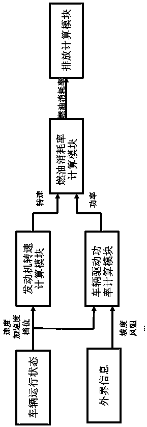
[0066] The steps of the present invention are:

[0067] 1.1. Engine speed calculation module

[0068] Obtain the vehicle gear information in real time, obtain the gear ratio of the gear according to the current gear, and then calculate the current engine speed according to formula (1).

[0069]

[0070] Where V eng Is the engine speed r tire Is the vehicle tire radius, I g Is the gear ratio of the vehicle, I 0 Is the differential magnification ratio, v car Is the vehicle speed.

[0071] 1.2. Vehicle power calculation module

[0072] After the engine speed is obtained, the required power for driving the vehicle is calculated according to formula (2). According to Newton's law, the required acceleration force is Ma·Ac, the force required to drive the vehicle to overcome the road gradient is Ma·g·sinω, and the force required to drive the vehicle to overcome the wind resistance is Ma·g·sinω. Force for The force required to drive the vehicle to overcome the rolling resistance is Ma·g·D r...


PUM


Abstract

The invention discloses a vehicle emission model modeling method suitable for intelligent network connection vehicle emission control, and belongs to the technical field of intelligent control. The invention aims at providing the vehicle emission model modeling method suitable for intelligent network connection vehicle emission control, which is used for connecting a vehicle with an engine throughdriving power and is suitable for controlling different control targets such as oil consumption and emission of the vehicle in an intelligent network connection environment. The method comprises thesteps of an engine rotating speed module (1), a vehicle power module (2), a fuel consumption rate module (3) and an emission module (4). From the perspective of an upper-layer vehicle, the vehicle isassociated with an engine through driving power according to the state of the vehicle, an engine fuel consumption rate model is established according to the power, and then a linear model of the fuelconsumption rate and emission is fitted according to data. The model established through adoption of the modeling method is simple and high in accuracy, and the modeling method is suitable for being applied to control over different control targets such as oil consumption and emission of the vehicle in the intelligent networking environment.

Description

Technical field [0001] The invention belongs to the technical field of intelligent control. Background technique [0002] Vehicle Intelligent Networking (Internet of Vehicles) is a huge interactive network composed of vehicle location, speed and route information. Through GPS, RFID, sensors, camera image processing and other devices, vehicles can complete the collection of their own environment and status information; through Internet technology, all vehicles can transmit their various information to the central processing unit; through computer technology, these vehicles The information can be analyzed and processed to calculate the best route for different vehicles, report road conditions in time, and arrange signal light cycles. Intelligent network contact information plays a very important role in improving road traffic efficiency, reducing automobile energy consumption and pollution, and reducing traffic accidents. In terms of improving road efficiency, intelligent transpo...

Claims


Application Information

Patent Timeline
Patent Type & Authority Applications(China)
IPC IPC(8): G06F30/15G06F30/20
Inventor 刘迪胡云峰张辉宫洵高金武郭洪艳陈虹
Owner JILIN UNIV
Why Eureka
Try Eureka