Installation, arrangement and construction method for distribution engineering transformer

A construction method and transformer technology, applied in the directions of transformer/reactor installation/support/suspension, switchgear, electrical components, etc., can solve the problems of large space occupation, inability to prevent falling, and inconvenient long-distance transportation, so as to reduce the overall The effect of occupying space, strengthening the carrying capacity, and facilitating long-distance transportation

Inactive Publication Date: 2020-06-09
王乐炯
View PDF10 Cites 0 Cited by
  • Summary
  • Abstract
  • Description
  • Claims
  • Application Information

AI Technical Summary

Problems solved by technology

[0003] However, the installation and layout construction methods of power distribution engineering transformers in the current market have the following problems in the operation process: a. When the traditional stone dry-hanging sealing and caulking treatment construction method fixes the transformer, the connecting equipment is connected and fixed to the utility pole. It adopts an embracing fixing method. The fixing method of this structure is single, the fixing is not firm enough, and it cannot achieve the effect of preventing falling; b. Because the connection equipment in the traditional stone dry-hanging sealing and caulking treatment construction method is integrated It takes up a lot of space and is not convenient for long-distance transportation. At the same time, the traditional connection equipment can only install a transformer, which cannot effectively use the installation space. At the same time, the bearing capacity of the connection equipment is weak, and it cannot be used for different types of transformer installations.

Method used


Image

  • Installation, arrangement and construction method for distribution engineering transformer
  • Installation, arrangement and construction method for distribution engineering transformer
  • Installation, arrangement and construction method for distribution engineering transformer

Examples


Embodiment Construction

[0033] In order to make the technical problems, technical solutions and beneficial effects to be solved by the present invention clearer, the present invention will be further described in detail below in conjunction with the accompanying drawings and embodiments. It should be understood that the specific embodiments described here are only used to explain the present invention, not to limit the present invention.

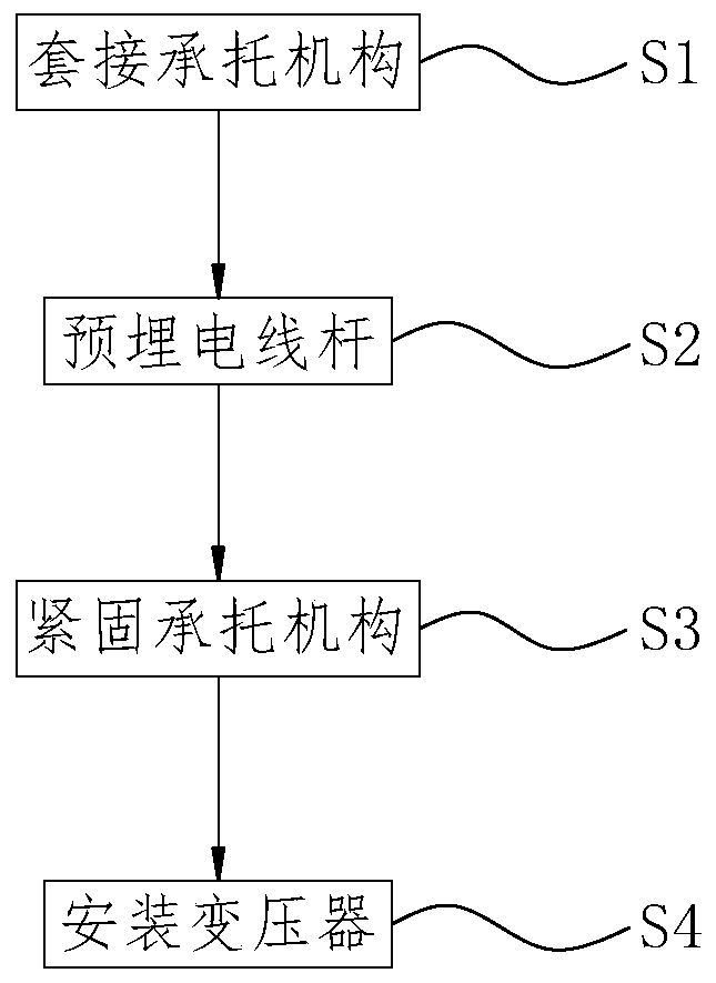
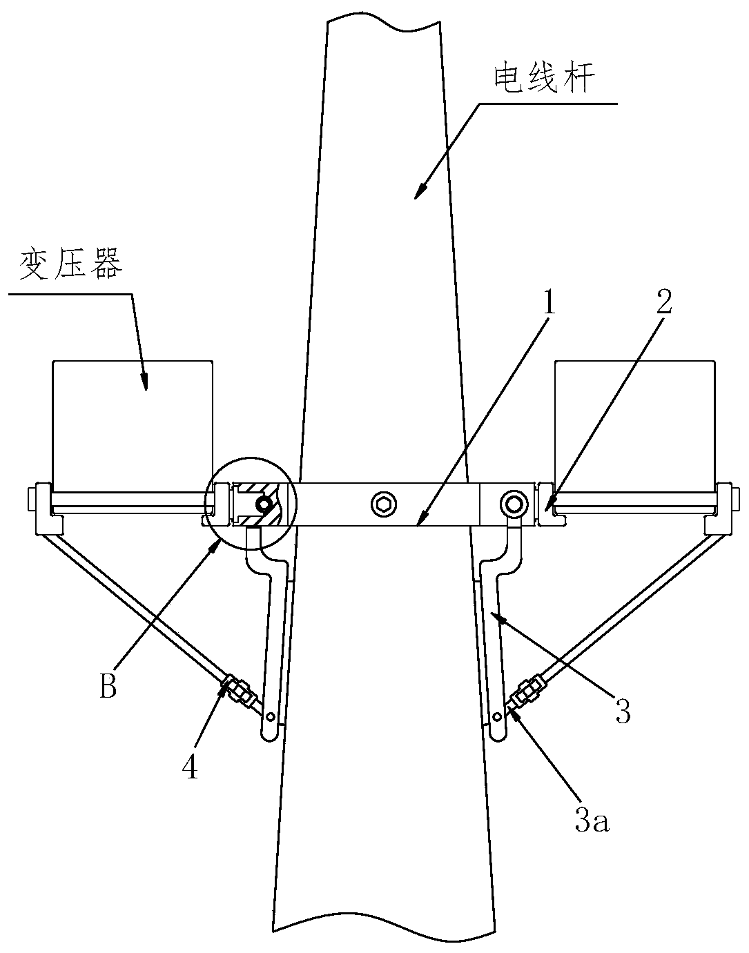
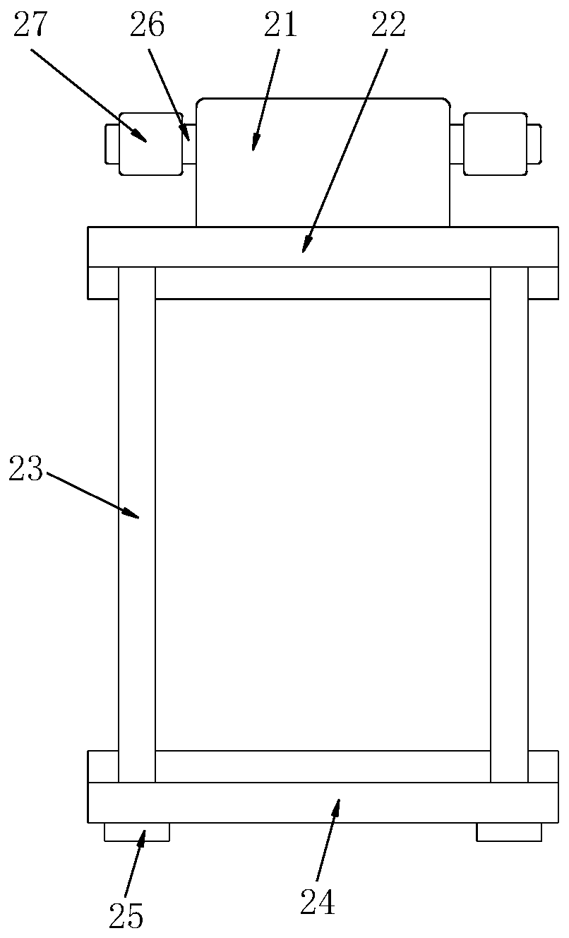
[0034] Refer to 1-9, a construction method for installation and layout of power distribution engineering transformers, which uses a power distribution engineering transformer installation device, the power distribution engineering transformer installation device includes a supporting mechanism 1, a fixing mechanism 2, an arc sticker For the plywood 3 and the locking mechanism 4, the specific method when using the above-mentioned power distribution engineering transformer installation device to install the transformer is as follows:

[0035] S1. Sleeve supporting me...


PUM


Abstract

The invention relates to an installation, arrangement and construction method for a distribution engineering transformer. A supporting mechanism, fixing mechanisms, an arc-shaped fitting plate and a locking mechanism are arranged; the fixing mechanisms are installed at the two ends of the supporting mechanism correspondingly; the outer wall of the supporting mechanism is movably connected with thearc-shaped fitting plate through a pin shaft; the arc-shaped fitting plate is connected with the fixing mechanism through the locking mechanism; rectangular connecting grooves are symmetrically formed in the two sides of the supporting outer ring; adjusting threaded rods are symmetrically mounted in the supporting outer ring; a supporting inner ring is mounted on the inner side of the supportingouter ring; worm wheels are symmetrically installed in the supporting inner ring; the upper end of the worm wheel is engaged with a worm; one end of the worm is welded to the end of the adjusting threaded rod; and circular grooves are formed in the inner walls of the two sides of the rectangular connecting groove. Through a multi-stage fixing structure, the installation stability of the transformer is effectively improved, the anti-falling effect is achieved, meanwhile, the installation function of multiple transformers is also achieved, and transformers of different models can be installed.

Description

technical field [0001] The invention relates to the technical field of transformer installation, in particular to a construction method for installing and arranging transformers in power distribution engineering. Background technique [0002] Power distribution is a link in the power system that is directly connected to users and distributes electric energy to users. The distribution system consists of distribution substations, high-voltage distribution lines, distribution transformers, low-voltage distribution lines and corresponding control and protection equipment. Among the components of the power distribution system, the installation of transformers is particularly important. Due to the large size of the transformer, the common installation process requires connecting equipment to fix it on the utility pole, and the installation stability of the transformer is entirely determined by the connecting equipment. [0003] However, the installation and layout construction m...

Claims


Application Information

Patent Timeline
Patent Type & Authority Applications(China)
IPC IPC(8): H01F27/06H02B3/00
CPCH01F27/06H02B3/00
Inventor 王乐炯李红梅
Owner 王乐炯
Why Eureka
Try Eureka