High-integration crimping type packaging power module with embedded clamp

A high-integration, power module technology, applied in the direction of electrical components, electrical solid-state devices, circuits, etc., can solve the problems of increasing the volume and cost of power conversion devices, requiring high operation accuracy, and invalid edge chip connections, etc., to avoid The effects of extreme temperature hotspots, reduction of stray parameters, and uniform pressure

Active Publication Date: 2020-06-09
ZHEJIANG UNIV
View PDF3 Cites 5 Cited by
  • Summary
  • Abstract
  • Description
  • Claims
  • Application Information

AI Technical Summary

Problems solved by technology

[0004] Although the clamp can achieve pressurization and maintain pressure, there are still the following shortcomings that need to be improved: (1) The clamp needs a support plate and a load-bearing plate that are similar in size to the crimping module, and additional fasteners and disc spring sets are required, increasing the The volume and use cost of the whole set of power conversion device are reduced; (2) Due to the centralized pressure maintenance method, the pressure between the chips inside the crimping module is unbalanced, and the chip in the center of the module is under greater force while the edge of the module The position of the chip is less stressed; (3) Due to the complex design of the fixture, the operation accuracy is high, and the pressure on the chip is unbalanced. Once the operation is wrong, the center chip will be damaged or the connection of the edge chip will be invalid.

Method used


Image

  • High-integration crimping type packaging power module with embedded clamp
  • High-integration crimping type packaging power module with embedded clamp
  • High-integration crimping type packaging power module with embedded clamp

Examples


Embodiment Construction

[0027] In order to better understand the present invention, the technical solutions of the present invention will be clearly and detailedly described below in conjunction with the accompanying drawings and specific embodiments.

[0028] In the description of the present invention, it should be noted that a series of terms describing orientation, such as "upper", "lower", "left", "right", "inner", "outer", "vertical", " "Horizontal" and so on all indicate the orientation or positional relationship based on the drawings, which are only for the convenience of description of the present invention, and do not indicate or imply that the devices or components in the present invention must have a specific orientation or be carried out in a specific orientation. construction or operation, and therefore should not be construed as limiting the invention.

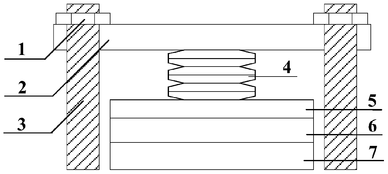
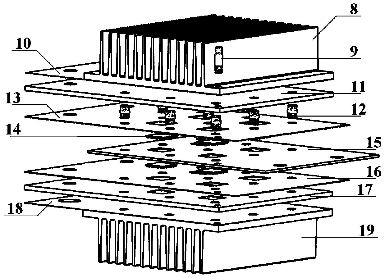
[0029] Such as figure 2 Shown is a schematic diagram of a specific implementation of the clamp-embedded highly integrated press-fit...


PUM


Abstract

The invention discloses a high-integration crimping type packaging power module with an embedded clamp. The high-integration crimping type packaging power module comprises a positive cooling fin, a direct-current positive copper bar, an alternating-current output copper bar, a direct-current negative copper bar and a negative cooling fin which are sequentially arranged from top to bottom, whereinsemiconductor chip units are symmetrically installed on the two sides of the alternating-current output copper bar, threaded holes penetrating through the crimping type module are evenly distributed in the peripheries of the semiconductor chip units, and through fastening by insulating double-head screws, external threads on the insulating double-head screws are meshed with internal threads of thethreaded holes to generate a crimping force. The embedded clamp is adopted to realize module crimping, and the copper bars and the radiator are used as components of the module, so that high power density and high integration level are realized; compared with a traditional crimping type packaging power module, the crimping type packaging power module in the technical scheme has the advantages that due to the fact that the design of the clamp is optimized, the design cost is reduced, the manufacturing process is simplified, and the crimping type packaging power module is used for achieving a high-power-density rectifier.

Description

technical field [0001] The invention belongs to the technical field of power electronic devices, and in particular relates to a high-integration pressure-bonding package power module embedded in a clamp. Background technique [0002] Press-fit packaging technology, compared with plastic-soldered packaging technology, has the application characteristics of free bonding wire, no solder layer, double-sided heat dissipation, short-circuit failure, etc. High-power semiconductor modules made of this packaging technology, such as thyristors (SCR ), integrated gate commutated thyristor (IGCT), press-fit insulated gate bipolar transistor (IGBT), etc., have the advantages of low thermal impedance, wide safe working area, and large rated power, and are widely used in flexible DC transmission and high-speed rail Transportation, long-distance wind power generation and other occasions with complex working conditions, harsh environments, and high reliability requirements. [0003] Due to ...

Claims


Application Information

Patent Timeline
Patent Type & Authority Applications(China)
IPC IPC(8): H01L23/40H01L23/367H01L25/07
CPCH01L23/3672H01L23/40H01L25/071
Inventor 李武华常垚罗皓泽朱安康陈宏何湘宁
Owner ZHEJIANG UNIV
Why Eureka
Try Eureka