Permanent magnet synchronous motor and assembling method

A permanent magnet synchronous motor and assembly method technology, which is applied to synchronous motors with static armatures and rotating magnets, electromechanical devices, electric components, etc. The problem of increasing torque pulsation and affecting the operation of mechanical equipment can achieve the effect of simple structure, reducing cogging torque and torque pulsation, and easy adjustment.

Inactive Publication Date: 2020-06-09
GREE ELECTRIC APPLIANCES INC
View PDF3 Cites 0 Cited by
  • Summary
  • Abstract
  • Description
  • Claims
  • Application Information

AI Technical Summary

Problems solved by technology

However, due to machining tolerances in the process of parts processing, the inner circle of the stator is generally elliptical. After the front end cover and the rear end cover are respectively fitted with the casing, the bearings of the front and rear end covers cannot be coaxial, resulting in the rotor and the rear end cover. The stator is not concentric
[0003] At this time, due to the eccentricity of the stator and the rotor, compared with the ideal stator and rotor, the eccentrically arranged stator and rotor will lead to increased cogging torque and torque ripple, which will affect the control accuracy of the permanent magnet synchronous motor, thereby affecting Operation of relevant machinery and equipment

Method used


Image

  • Permanent magnet synchronous motor and assembling method
  • Permanent magnet synchronous motor and assembling method
  • Permanent magnet synchronous motor and assembling method

Examples


Embodiment 1

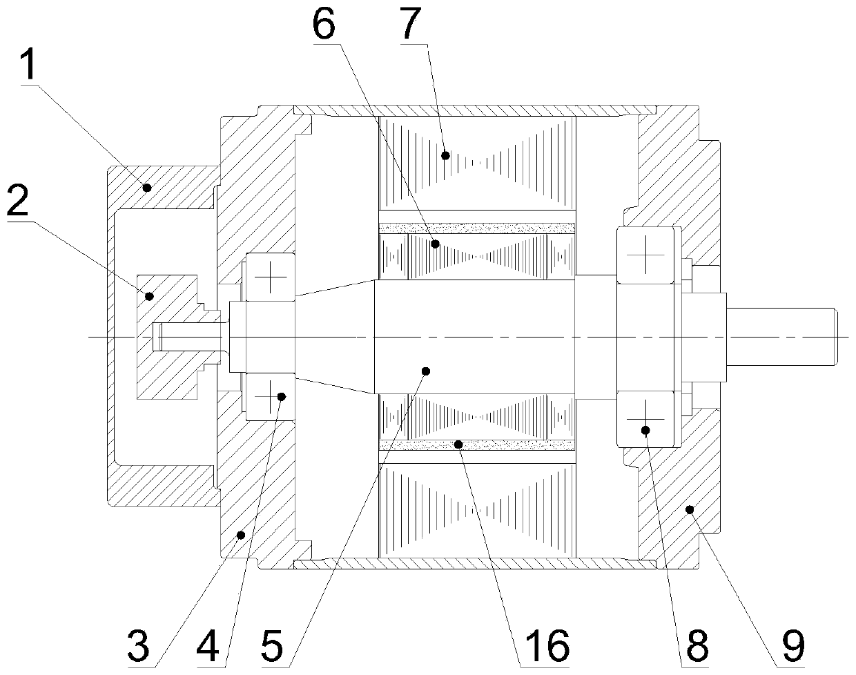
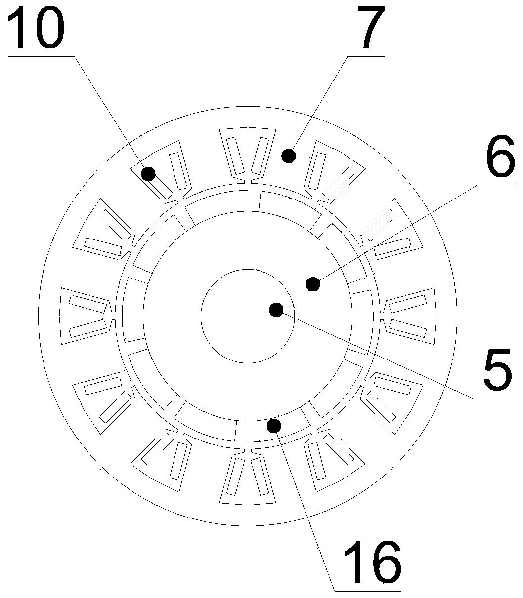
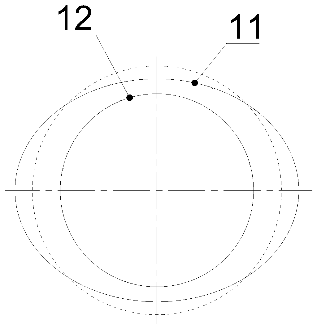
[0037] see Figure 4-Figure 7 , a permanent magnet synchronous motor according to this embodiment, comprising a casing, a stator 7, a rotor 6, a magnetic steel 16, a rotating shaft 5, a front end cover 9 and a rear end cover 3; the inner circle of the stator 7 is an ellipse; the rotor 6 is arranged in the stator 7, and the center of the rotor 6 is arranged on the minor semi-axis centerline of the inner circle of the stator 7 (and the center of the rotor 6 is not at the same point as the center of the inner circle of the stator 7). Wherein, the offset distance between the center of the rotor 6 and the center of the inner circle of the stator 7 is 0.01mm-0.1mm.

[0038] In the permanent magnet synchronous motor of this embodiment, by offsetting the rotor 6 to the short semi-axis of the ellipse 11 in the stator 7, the cogging torque and torque ripple are effectively reduced, which is conducive to improving the accuracy of the motor, thereby improving the performance of the corres...

Embodiment 2

[0051] In the step (4) of the assembly method of the permanent magnet synchronous motor, the front bearing 8 and the rear bearing 4 are respectively pressed into the corresponding positions of the rotor 6 by using a press bearing tooling and a hand press. Using a hand press to install the front bearing 8 and the rear bearing 4 is convenient for manual control of the installation accuracy, and is beneficial for workers to adjust according to the actual assembly situation.


PUM


Abstract

The invention provides a permanent magnet synchronous motor and an assembling method, which particularly relate to the technical field of motors. The permanent magnet synchronous motor comprises a casing, a stator, a rotor, magnetic steel, a rotating shaft, a front end cover and a rear end cover, wherein the inner circle of the stator is elliptical; the rotor is arranged in the stator; and the center of the rotor is arranged on the center line of the minor semi-axis of the inner circle of the stator. According to the permanent magnet synchronous motor, the rotor deviates towards the minor semi-axis of the ellipse in the stator, so that the cogging torque and the torque pulsation are effectively reduced, the precision of the motor is improved, and the operation precision of corresponding equipment is improved.

Description

technical field [0001] The invention relates to a motor, in particular to a permanent magnet synchronous motor and an assembly method. Background technique [0002] The traditional permanent magnet synchronous motor is mainly composed of a casing, a stator 7, a magnetic steel 16, a rotor 6, a front end cover 9, a rear end cover 3 and a rotating shaft 5, as figure 1 shown. Ideally, the inner circle of the stator 7 is an ideal circle, and the center position of the rotor 6 is on the same straight line as the center position of the inner cylinder of the stator 7, that is, the centers of the stator 7 and the rotor 6 coincide, as figure 2 and image 3 shown. However, due to machining tolerances in the process of parts processing, the inner circle of the stator is generally elliptical. After the front end cover and the rear end cover are respectively fitted with the casing, the bearings of the front and rear end covers cannot be coaxial, resulting in the rotor and the rear end...

Claims


Application Information

Patent Timeline
Patent Type & Authority Applications(China)
IPC IPC(8): H02K21/14H02K11/21H02K15/16
CPCH02K11/21H02K15/16H02K21/14
Inventor 吴帮超杨文德杨一刘赫邱克难
Owner GREE ELECTRIC APPLIANCES INC
Why Eureka
Try Eureka