Filter apparatus

A filter equipment and filter technology, which is applied in the direction of filtration separation, membrane filter, fixed filter element filter, etc., can solve the problems of affecting fluid treatment, cost consumption, large structure, etc., and achieve the solution of stress cracks, compact layout, uniform The effect of heat distribution

Active Publication Date: 2020-06-09
HYDAC PROCESS TECH
View PDF6 Cites 6 Cited by
  • Summary
  • Abstract
  • Description
  • Claims
  • Application Information

AI Technical Summary

Problems solved by technology

[0005] The solutions described above are experientially bulky and are often complex and therefore expensive to install on-site from an installation point of view
Due to the different installation positions of the filter device and the associated bypass filter, even if they are arranged next to each other, different thermal operating conditions occur, which can adversely affect the fluid handling, especially in the area of ​​fluid filtration

Method used


Image

  • Filter apparatus
  • Filter apparatus
  • Filter apparatus

Examples


Embodiment Construction

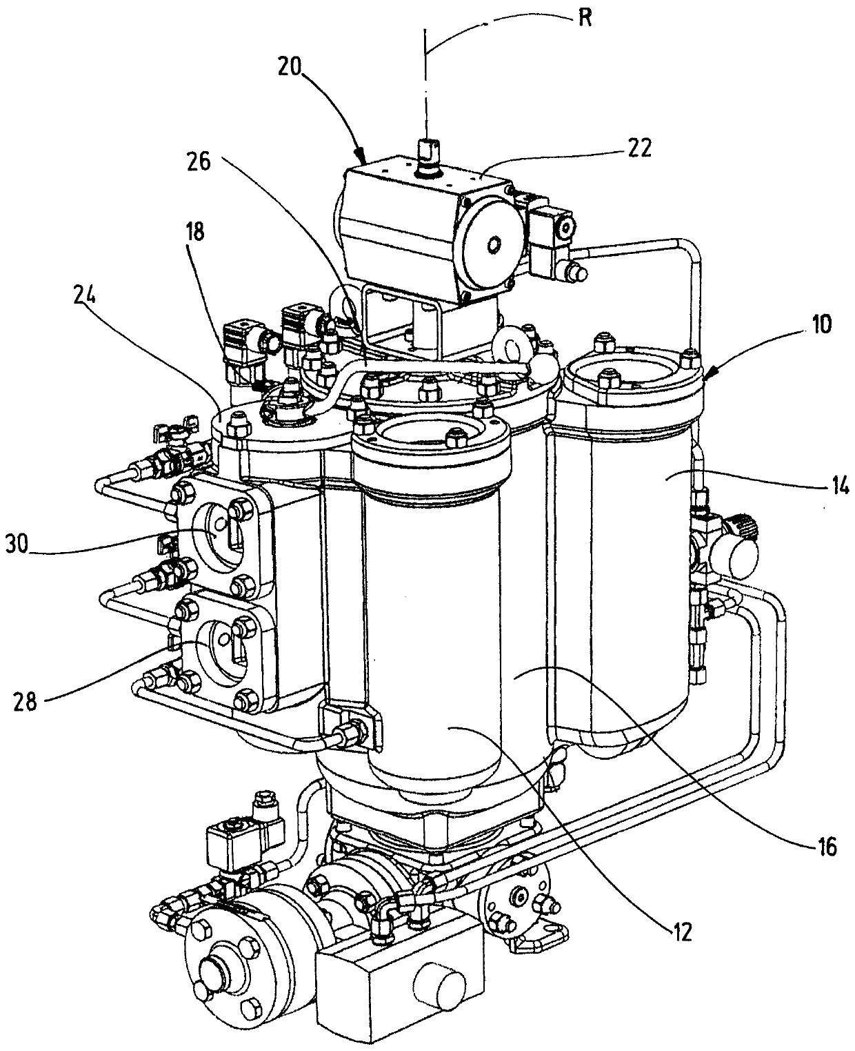
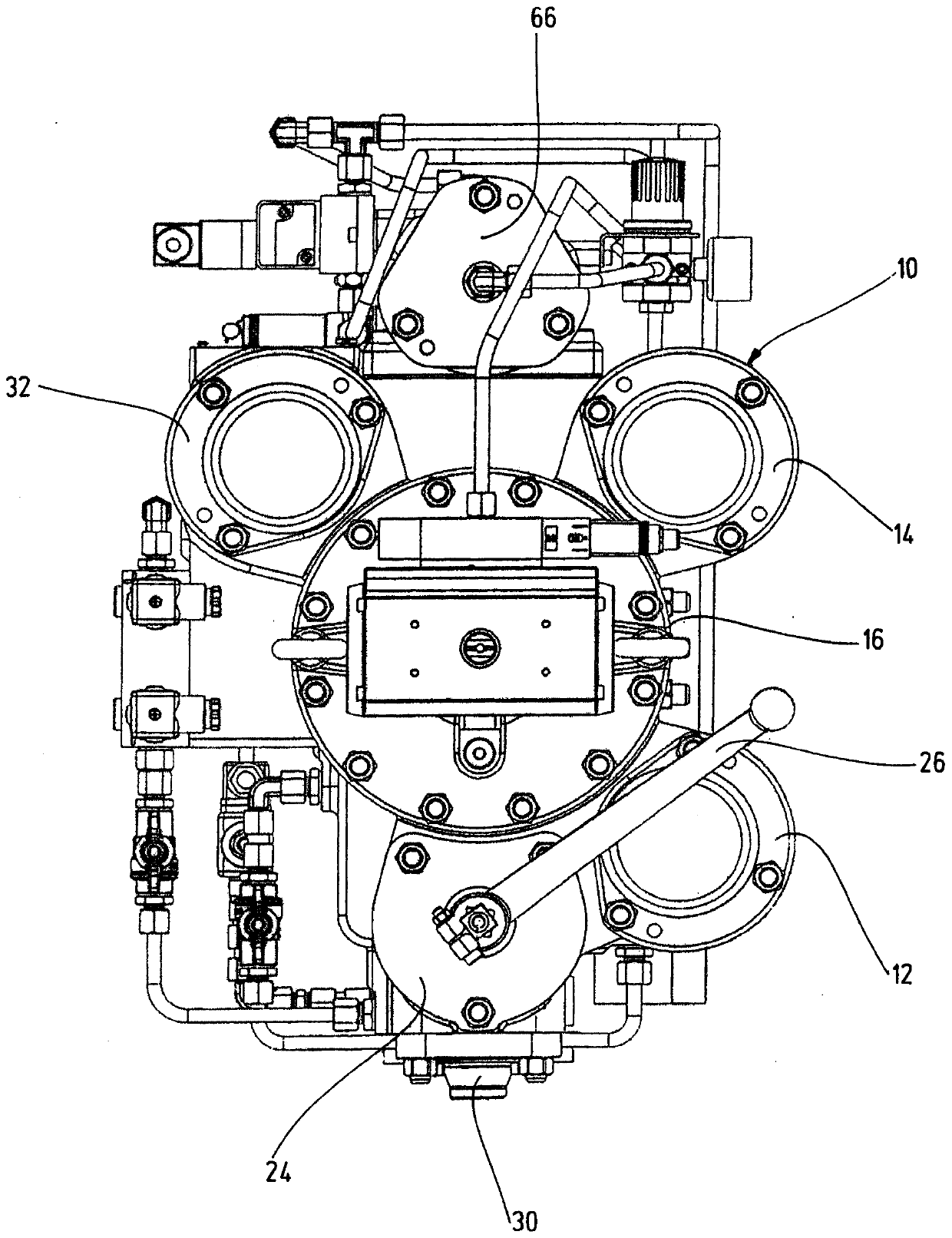
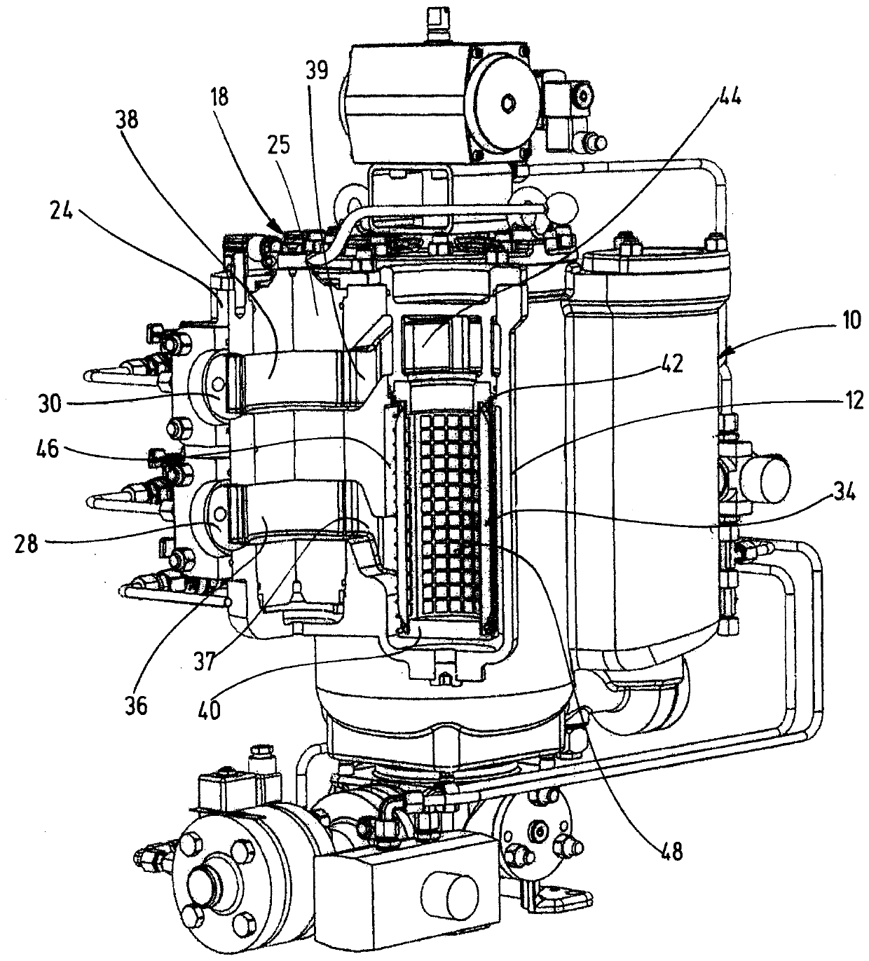
[0031] figure 1 Shows a general view of a filter device according to the invention with a filter housing 10 having three filter chambers (a first filter chamber 12, a second filter chamber 14 and a third filter chamber Filter chamber 32 (see figure 2 )), spindle housing 24, housing body 16 and drive unit 22. Provided on the spindle housing 24 is a fluid inlet indicated by 28 for supplying the fluid to be cleaned, and an outlet indicated by 30 for discharging the cleaned fluid. One filter element 34 is installed in each filter chamber 12, 14, 32 (see image 3 ), 60 (see Figure 4 ). The central component of the filter device is the conversion device 18, which is received by the main shaft housing 24 and figure 1 Only the operating device in the form of a hand lever 26 is visible in the conversion device. Furthermore, a backflushing device 20 is provided on the filter device, which is accommodated in the housing body 16 and figure 1 The drive unit 22 arranged above the h...


PUM


Abstract

The invention relates to a filter apparatus for cleaning particulate contaminants out of a fluid flow, having a plurality of filter elements (34, 60), which, received in filter chambers (12, 14, 32) as a component of a common filter housing (10), group about a backwash device (20), which, in order to receive a backwash volume, has a piston accumulator (56), in the accumulator housing (64) of whicha piston (57) is guided in a longitudinally movable manner, said piston, actuated by a pressure medium, forwarding the backwash volume stored in the accumulator housing (64) to at least one filter element (60), which is to be backwashed for cleaning thereof, via a backwash device (20), which also undertakes removal of the backwash volume from the filter apparatus, characterized in that a specificfilter element, as a bypass filter element (34), which is selected from the plurality of filter elements (34, 60), solely undertakes the particle cleaning after actuating a changeover device (18), and the other filter elements (60) are excluded from said cleaning.

Description

technical field [0001] The invention relates to a filter device for cleaning a fluid flow of particulate contamination, the filter device having a plurality of filter elements which are accommodated in a filter as part of a common filter housing In the chamber and around the backflushing device, the backflushing device has a piston accumulator for receiving the backflushing volume, in the accumulator housing of which the piston is displaceably guided in the longitudinal direction , the piston transmits the backflush volume stored in the accumulator housing via a backflush device via a backflush device to at least one filter element to be backwashed for its cleaning, which is also used to backwash The volume is derived from the filter device. Background technique [0002] Such a filter device is known, for example, from WO 2012 / 150011 A1. The known filter device comprises a pressure control device for assisting the backwashing of the individual filter elements, the pressure...

Claims


Application Information

Patent Timeline
Patent Type & Authority Applications(China)
IPC IPC(8): B01D35/12B01D35/147B01D29/15B01D29/52B01D29/66
CPCB01D35/12B01D35/147B01D29/15B01D29/52B01D29/665B01D29/668B01D29/114B01D2201/0446B01D2201/287
Inventor S·赫里茵H-J·林根
Owner HYDAC PROCESS TECH
Why Eureka
Try Eureka