
Thermal efficiency automatic optic inspection machine

A thermal efficiency, testing room technology, applied in conveyor objects, cleaning devices, transportation and packaging, etc., can solve the problems of inability to detect materials, chaotic blanking and testing processes, and inability to separate qualified and unqualified products. Reasonable structure, avoid confusion, and detect comprehensive effects

Inactive Publication Date: 2020-06-12
深圳市中科华工科技有限公司
View PDF7 Cites 2 Cited by
  • Summary
  • Abstract
  • Description
  • Claims
  • Application Information

AI Technical Summary

Problems solved by technology

[0006] The purpose of the present invention is to provide a thermal efficiency full inspection machine to solve the problems in the above-mentioned background technology that the material cannot be inspected in an all-round way, the separation of qualified and unqualified products cannot be realized, and the confusion of blanking and inspection process is easy to occur. The problem

Method used


Image

  • Thermal efficiency automatic optic inspection machine
  • Thermal efficiency automatic optic inspection machine
  • Thermal efficiency automatic optic inspection machine

Examples


Embodiment Construction

[0028] The following will clearly and completely describe the technical solutions in the embodiments of the present invention with reference to the accompanying drawings in the embodiments of the present invention. Obviously, the described embodiments are only some, not all, embodiments of the present invention. Based on the embodiments of the present invention, all other embodiments obtained by persons of ordinary skill in the art without making creative efforts belong to the protection scope of the present invention.

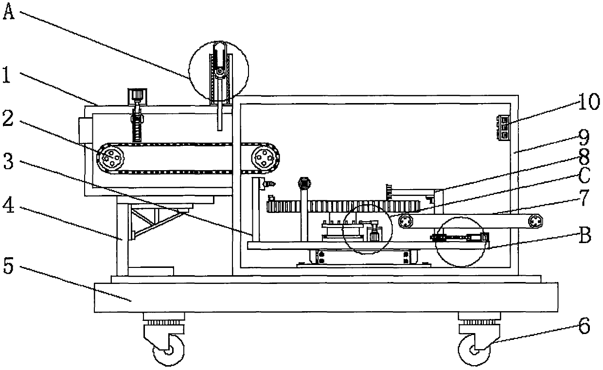
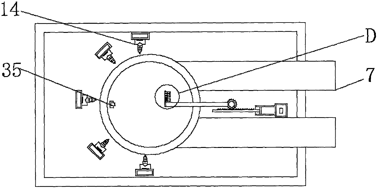
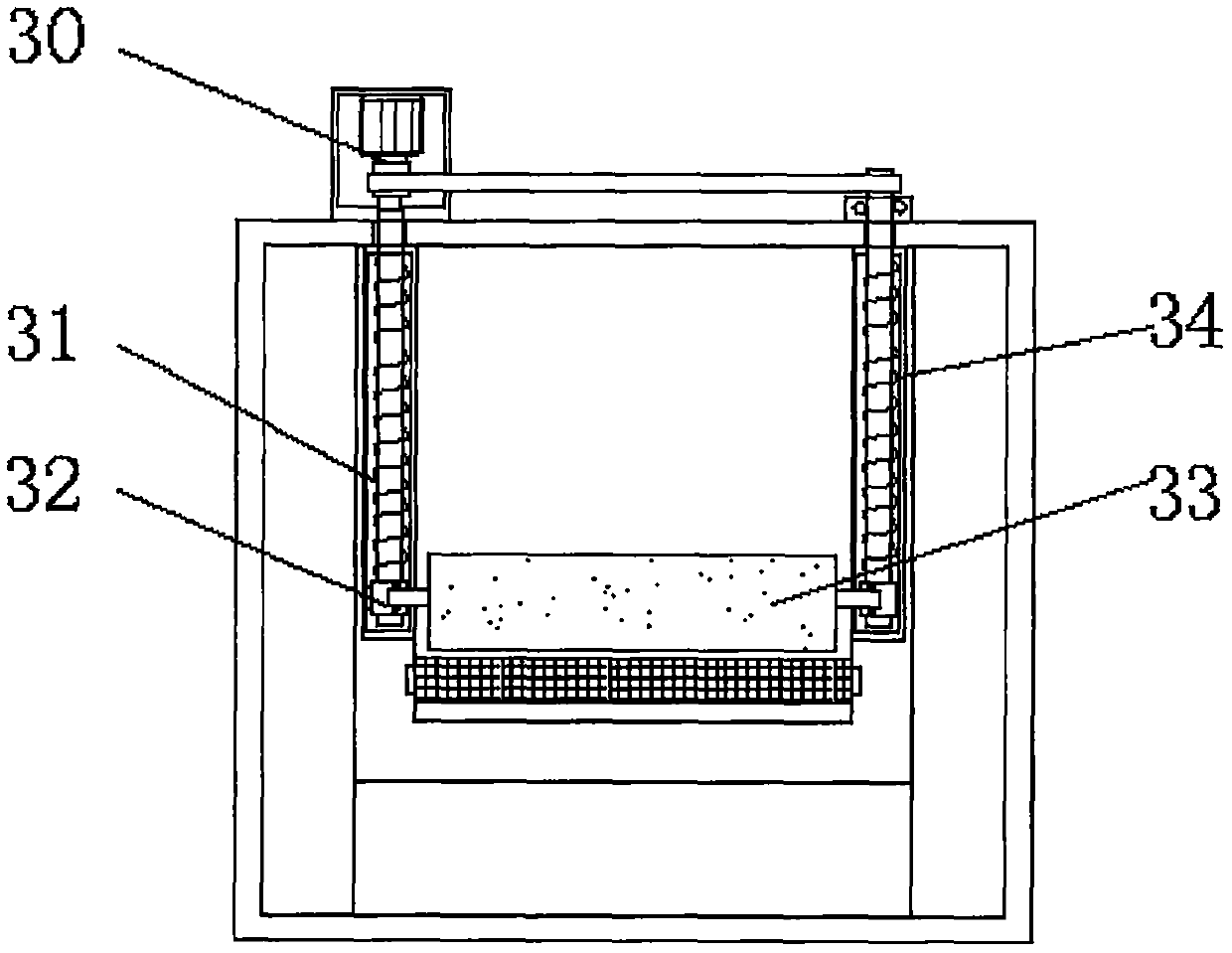
[0029] see Figure 1-8 , an embodiment provided by the present invention: a thermal efficiency full inspection machine, including a feed box 1, a first conveyor belt 2, a workbench 3, a base plate 5, a detection chamber 9 and a CCD detection camera 14, two bottom ends of the base plate 5 A universal wheel 6 is provided at the end, and a braking mechanism is arranged inside the universal wheel 6;

[0030] Universal wheels 6 are provided at both ends of the bot...


PUM


Abstract

The invention discloses a thermal efficiency automatic optic inspection machine. The thermal efficiency automatic optic inspection machine comprises a feeding box, a first conveyor belt, a worktable,a bottom plate, a detection chamber and CCD detection cameras, wherein one side of the top end of the bottom plate is provided with the detection chamber, the interior of the detection chamber is provided with the worktable, and one side of the worktable is annularly provided with the multiple CCD detection cameras through installation pieces; the center of the top end of the worktable is providedwith a rotating shaft, the top end of the rotating shaft is provided with a detection table, one side of the top end of the detection table is provided with an infrared sensor, the portion, below thedetection table, of the interior of the detection chamber is symmetrically provided with second conveyor belts, and the upper end of one side of the interior of the detection chamber is provided witha single-chip microcomputer; and the top end of an installation frame is provided with the feeding box. According to the thermal efficiency automatic optic inspection machine, by driving a second drive motor, intermittent rotation of the detection table is realized through the cooperation of arranged vertical rods and a stop rod, then, materials are detected in all directions through the annularly arranged CCD detection cameras, and thus detection is more comprehensive.

Description

technical field [0001] The invention relates to the technical field of testing equipment, in particular to a thermal efficiency full testing machine. Background technique [0002] The automatic optical inspection machine, also known as the optical inspection machine, CCD inspection machine, etc., is an equipment that detects common defects encountered in welding production based on optical principles. The main thing is to use the camera to take pictures of the product to get the value. Now there is a thermal efficiency full inspection machine that is widely used, but there are many problems or defects in the existing thermal efficiency full inspection machine. [0003] First, the traditional thermal efficiency full inspection machine cannot conduct all-round inspection of materials, and the inspection process is not comprehensive. [0004] Second, the traditional thermal efficiency full inspection machine does not have an intelligent separation module, so it cannot separate...

Claims


Application Information

Patent Timeline
Patent Type & Authority Applications(China)
IPC IPC(8): B07C5/00B07C5/02B07C5/36B65G45/18
CPCB07C5/00B07C5/02B07C5/361B07C5/362B65G45/18
Inventor 黎文灏王磊张群张晶卢丽王涛
Owner 深圳市中科华工科技有限公司
Learn More