Mechanical manufacturing die plate stamping perforating device

A technology of mechanical manufacturing and perforation device, applied in the direction of manufacturing tools, punching machines, perforation tools, etc., can solve the problems of affecting perforation, weak point of force at the bottom of the die plate, inconvenient to take out the die plate, etc., to achieve the effect of easy installation and replacement

Inactive Publication Date: 2020-06-12
平湖市超凯科技有限公司
View PDF1 Cites 0 Cited by
  • Summary
  • Abstract
  • Description
  • Claims
  • Application Information

AI Technical Summary

Problems solved by technology

[0004] The object of the present invention is to provide a punching and perforating device for mechanically manufacturing mold plates to solve the problem that the texture of the belt feeding proposed in the above background is relatively soft, and the force point at the bottom of the die plate is weak during the punching and perforating process, which affects the perforation and is not convenient for the mold plate. The problem of taking out

Method used


Image

  • Mechanical manufacturing die plate stamping perforating device
  • Mechanical manufacturing die plate stamping perforating device
  • Mechanical manufacturing die plate stamping perforating device

Examples


Embodiment Construction

[0019] The technical solutions in the embodiments of the present invention will be clearly and completely described below in conjunction with the accompanying drawings in the examples of the present invention. Obviously, the described embodiments are only some of the embodiments of the present invention, not all of them. Based on the embodiments of the present invention, all other embodiments obtained by persons of ordinary skill in the art without creative efforts fall within the protection scope of the present invention.

[0020] see Figure 1-3 , the present invention provides a technical solution:

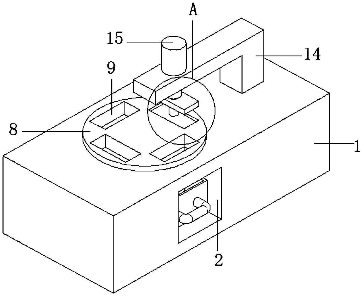
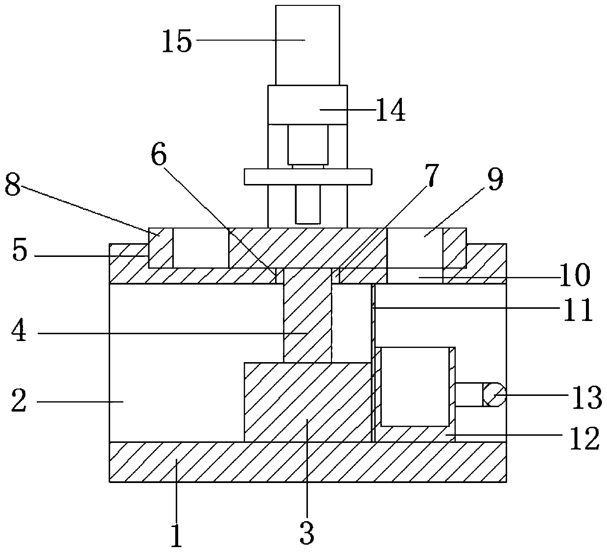
[0021] A kind of mechanical manufacturing mold plate stamping perforation device, such as figure 1 and figure 2 As shown, it includes a base 1 and a mold plate 20. The side of the base 1 is provided with a penetrating moment groove 2. A servo motor 3 is fixed in the center of the bottom end of the penetrating moment groove 2. The output end of the servo motor 3 is connected ...


PUM


Abstract

The invention discloses a mechanical manufacturing die plate stamping perforating device, and belongs to the technical field of mechanical die machining. The mechanical manufacturing die plate stamping perforating device comprises a base and a die plate; the side surface of the base is provided with a through rectangular groove, a servo motor is fixed to the center of the bottom end of the throughrectangular groove, and the output end of the servo motor is connected with a rotary shaft; the top end of the base is provided with a circular groove, the center of the bottom end of the circular groove is provided with a through hole, and a bearing is installed in the through hole; the end of the rotary shaft is rotationally connected with a placement disc through the bearing, and the placementdisc is rotationally arranged in the circular groove; the top end of the placement disc is provided with four installation grooves, and the installation grooves penetrate through the placement disc;the top end of the through rectangular groove is provided with a communication groove, and a partition plate is fixed to the bottom end of the through rectangular groove; the position, right facing the communication groove, of the bottom end of the through rectangular groove is provided with a collection box; an L-shaped bracket is fixed to the top end of the base; a stamping air cylinder is fixedto the top end of the L-shaped bracket, a piston rod is movably connected to the interior of the stamping air cylinder, and an electromagnet disc is fixed to the end of the piston rod; and the end ofthe electromagnet disc is magnetically connected with a stamping plate, and the bottom end of the stamping plate is provided with a perforating head.

Description

technical field [0001] The invention relates to the technical field of mechanical mold processing, in particular to a stamping and perforating device for mechanically manufacturing mold plates. Background technique [0002] Stamping processing is a production technology that uses the power of conventional or special stamping equipment to directly subject the sheet to deformation force and deform in the mold, so as to obtain product parts of a certain shape, size and performance. In the process of mechanical manufacturing mold processing, it is necessary to perform stamping and perforation processing on mechanical manufacturing molds. Every time the stamping process is performed, it is necessary to manually or rely on auxiliary equipment to take the workpiece template, which increases the operation process of stamping processing. [0003] At present, the Chinese patent with the application number CN201821356516.X discloses a mechanically manufactured die plate stamping and pe...

Claims


Application Information

Patent Timeline
Patent Type & Authority Applications(China)
IPC IPC(8): B21D28/26B21D28/34B21D43/00B21D43/22B21D37/04B30B1/38
CPCB21D28/26B21D28/34B21D37/04B21D43/003B21D43/22B30B1/38
Inventor 陈礼成
Owner 平湖市超凯科技有限公司
Why Eureka
Try Eureka