Cutting mechanism for beveling machine

A technology of cutting mechanism and beveling machine, applied in the direction of shearing device, accessory device of shearing machine, pipe shearing device, etc., can solve the problems of inconvenient cutting work, affecting processing efficiency, pipe fixing, etc. Scope of application, the effect of reducing the occupied space

Inactive Publication Date: 2020-06-12
LANZHOU CITY UNIV
View PDF1 Cites 1 Cited by
  • Summary
  • Abstract
  • Description
  • Claims
  • Application Information

AI Technical Summary

Problems solved by technology

[0005] The purpose of the present invention is to provide a cutting mechanism for beveling machines to solve the problem of the existing cutting mechanism for beveling machines. When cutting pipes of different sizes, different clamps need to be used for fixing. The special fixture device on the beveling machine affects the processing efficiency, so that the applicable range of the device is small, and the fixture takes up a large space, which is not convenient for the later cutting work; the existing cutting mechanism used for the beveling machine, when cutting, because the blade surrounds the pipe , so that the torsion force on the pipe is relatively large, and workers cannot fix the pipe with ordinary pliers, and need special clamps to fix it, resulting in inconvenient material removal after cutting and complicated operation; the existing cutting mechanism and device for beveling machine The height position cannot be adjusted, and it cannot be used by workers of different heights, and one device can only be operated by a single worker, which reduces work efficiency.

Method used


Image

  • Cutting mechanism for beveling machine
  • Cutting mechanism for beveling machine
  • Cutting mechanism for beveling machine

Examples


Embodiment Construction

[0031] The technical solutions of the present invention will be clearly and completely described below in conjunction with the embodiments. Apparently, the described embodiments are only some of the embodiments of the present invention, not all of them. Based on the embodiments of the present invention, all other embodiments obtained by persons of ordinary skill in the art without creative efforts fall within the protection scope of the present invention.

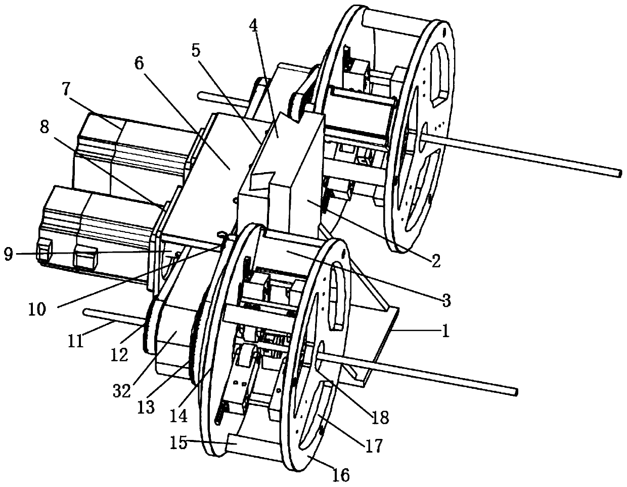
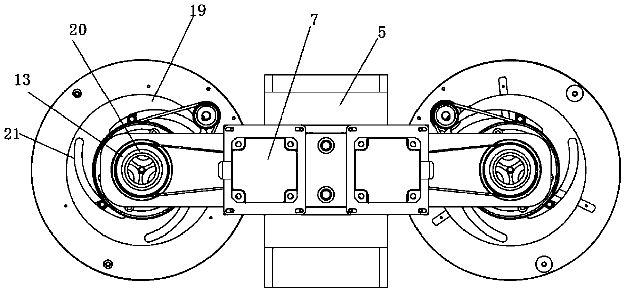
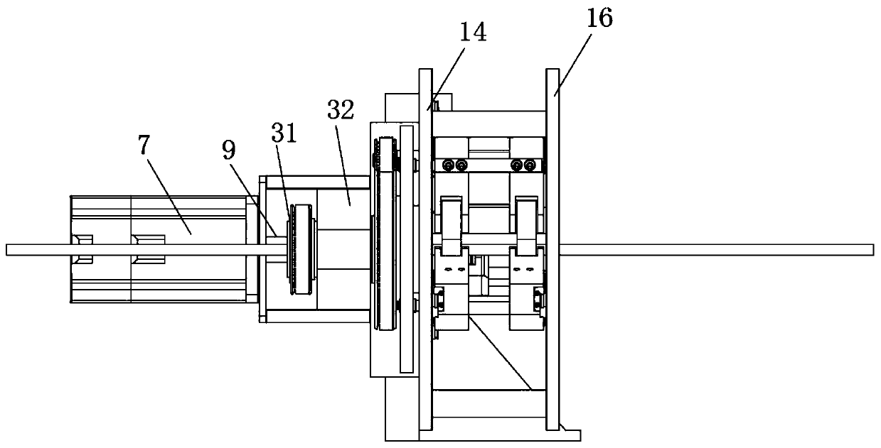
[0032] Such as Figure 1-5 As shown, a cutting mechanism for a beveling machine includes an underframe 1 and a support plate 2, the top of the underframe 1 is provided with a support plate 2, and a side wall on one side of the support plate 2 is provided with a slide rail 4 , the slide rail 4 is provided with a sliding sleeve 5, and the side wall of the slide rail 4 opposite to the support plate 2 is fixedly provided with a horizontal plate 6, and one end of the horizontal plate 6 is fixedly connected with two motor seats 8...


PUM


Abstract

The invention discloses a cutting mechanism for a beveling machine. The cutting mechanism for the beveling machine comprises a bottom frame and a supporting plate, the supporting plate is arranged atthe top of the bottom frame, a sliding rail is arranged on the side wall of one side of the supporting plate, a sliding sleeve is arranged on the sliding rail, a transverse plate is fixedly arranged on the side wall of the side, opposite to the supporting plate, of the sliding rail, two motor bases are fixedly connected to one end of the transverse plate, a pipe is clamped by pliers to prevent rotation, a second rotating shaft is driven by the output end of a second motor to rotate, a second driving wheel is driven by the second rotating shaft to rotate, a second transmission wheel is driven by the second driving wheel to rotate through a chain, so that a sleeve rotates, then a working disc and a cover disc are driven to rotate, a blade on a mounting frame cuts the pipe in a surrounding mode, cutting work of the pipe is achieved, cutting is convenient, due to the fact that the blades conduct surrounding cutting, torsional force borne by the pipe is small, a worker can fix the pipe through common pliers, use is convenient, after cutting is completed, material taking is easy, and operation is easy.

Description

technical field [0001] The invention relates to the field of beveling machine equipment, in particular to a cutting mechanism for beveling machines. Background technique [0002] The beveling machine is a special tool for chamfering and beveling pipes or plates on the welding front end, which solves the shortcomings of irregular angles, rough slopes, and loud working noises in flame cutting and grinding machine grinding. Currently used beveling machines take up a lot of space and are inconvenient to operate. [0003] The existing cutting mechanism for the beveling machine needs to use different fixtures for fixing when cutting pipes of different sizes. The replacement of the special fixture device on the beveling machine will affect the processing efficiency, so that the applicable range of the device is small, and the fixture It takes up a lot of space and is not convenient for later cutting work; the existing cutting mechanism used for beveling machines, when cutting, bec...

Claims


Application Information

Patent Timeline
Patent Type & Authority Applications(China)
IPC IPC(8): B23D21/00B23D33/02B23K33/00
CPCB23D21/00B23D33/02B23K33/00
Inventor 李鲤杨斌刘善春
Owner LANZHOU CITY UNIV
Why Eureka
Try Eureka