A cutting device for door and window production

A cutting, door and window technology, applied in the direction of positioning devices, manufacturing tools, metal processing machinery parts, etc., can solve the problems that the end of the profile cannot be supported, the profile is easy to shake, and the labor intensity of the workers is high, so as to improve flexibility and increase the overall Strength, effect of improving cleanliness

Active Publication Date: 2021-08-27
烟台红旗瑞景门窗有限公司
View PDF8 Cites 0 Cited by
  • Summary
  • Abstract
  • Description
  • Claims
  • Application Information

AI Technical Summary

Problems solved by technology

[0003] The door and window profile cutting equipment in the prior art usually cuts one end of the profile first, then turns the profile over and then cuts the other end. This cutting method is inefficient and the labor intensity of the workers is high.
In addition, for longer profiles, it is necessary to cut them into small sections, and then cut each small section of profiles. When cutting longer profiles, the existing device cannot support the tail end of the profile, so that the profile cutting prone to shaking

Method used


Image

  • A cutting device for door and window production
  • A cutting device for door and window production
  • A cutting device for door and window production

Examples


Embodiment 1

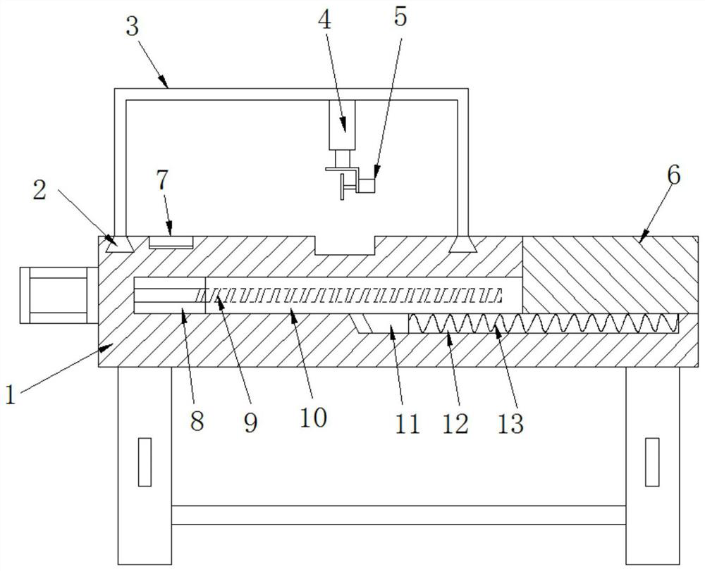
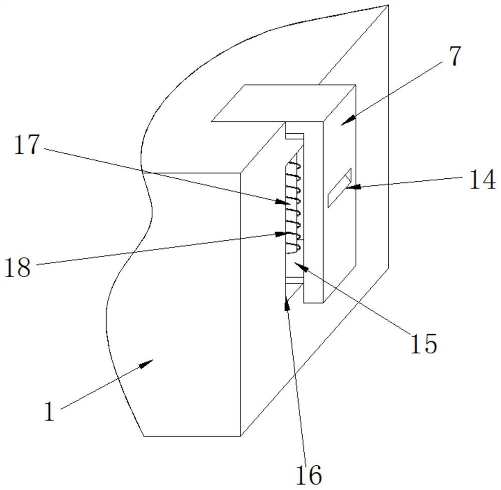
[0026] refer to Figure 1-3 , a cutting device for door and window production, comprising a base 1, a cutting mechanism 5 is arranged above the top of the base 1, a cutting groove is opened on the outer wall of the top of the base 1 below the cutting mechanism 5, and the outer walls of the two sides of the base 1 are opened. There is an installation groove 16, and a clamping mechanism is arranged in the installation groove 16. The right side of the abutment 1 is provided with a fitting support platform 6, and the bottom end of the outer wall on the left side of the support platform 6 is fixed with an extension plate 10, and the extension plate 10 is movably plugged in. In the storage groove 8 opened in the base 1, the end of the extension plate 10 away from the support table 6 is connected with a transverse drive mechanism, and the bottom of the extension plate 10 is fixed with a guide block 11, and the guide block 11 is movably inserted on the right side of the base 1. In the...

Embodiment 2

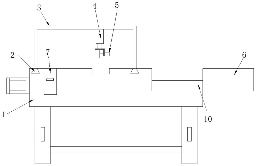
[0031] refer to Figure 4 , a cutting device for door and window production. The difference between this embodiment and Embodiment 1 is that the outer wall of one side of the abutment 1 is close to the position of the support platform 6. There is also an embedding groove 20, and the embedding groove 20 is fixed with an extension plate 10 The brush 21 attached to the outer wall of the top, and the support platform 6 has a material guide port 19 with the same level as the brush 21, and the inner wall at the bottom of the material guide port 19 is provided with a material guide slope.

[0032] The working principle of this embodiment: the brush 21 can form opposite movement with the support table 6 for storage work, so that the brush 21 can clean and push the impurities on the upper surface of the extension plate 10, and the impurities move along the upper surface of the extension plate 10 to The material guide port 19 discharges impurities along the material guide slope to impro...


PUM


Abstract

The invention discloses a cutting device for door and window production, which comprises a base, a cutting mechanism is arranged above the top of the base, a cutting groove is opened on the outer wall of the top of the base below the cutting mechanism, and the outer walls on both sides of the base are There is an installation groove, and a clamping mechanism is provided in the installation groove. A fitting support platform is provided on the right side of the abutment, and an extension plate is fixed at the bottom of the outer wall on the left side of the support platform, and the extension plate is movably inserted into the abutment In the storage slot opened, the end of the extension plate far away from the support platform is connected with a transverse drive mechanism. The bottom of the extension plate is fixed with a guide block, and the guide block is movably inserted into the guide slot opened on the right side of the abutment. The present invention can increase the overall supporting length of the abutment, which is convenient for placing and supporting some longer profiles, and furthermore can improve the stability of profile cutting and avoid falling.

Description

technical field [0001] The invention relates to the technical field of door and window production, in particular to a cutting device for door and window production. Background technique [0002] The use of profiles to make doors and windows is usually to make profiles into square or rectangular frames, and then install glass or other frames in the frames. During production and assembly, the ends of the profiles are cut into bevels of 45 degrees and 135 degrees respectively. When the 45-degree beveled end of one profile is aligned with the 135-degree beveled end of the other profile, the door and window profile processing angle machine is used for punching and riveting, so that the two profiles form The state of the 90-degree angle. [0003] The door and window profile cutting equipment in the prior art usually cuts one end of the profile first, and then cuts the other end after the profile is reversed. This cutting process is inefficient and labor-intensive. In addition, ...

Claims


Application Information

Patent Timeline
Patent Type & Authority Patents(China)
IPC IPC(8): B23D79/00B23Q3/06B23Q1/74B23Q11/00
CPCB23D79/00B23Q1/74B23Q3/064B23Q11/0042
Inventor 赵艳
Owner 烟台红旗瑞景门窗有限公司
Why Eureka
Try Eureka