
Torsion beam limit block structure and limit system
A limit block and torsion beam technology, which is applied in interconnection systems, vehicle components, cantilever mounted on pivots, etc., can solve the problem of high body strength requirements, easy damage to the buckle of the limit block, and user influence on vehicle products Word-of-mouth and other issues, to avoid the risk of abnormal noise and improve the driving experience
- Summary
- Abstract
- Description
- Claims
- Application Information
AI Technical Summary
Problems solved by technology
Method used
Image

Examples
Embodiment 1
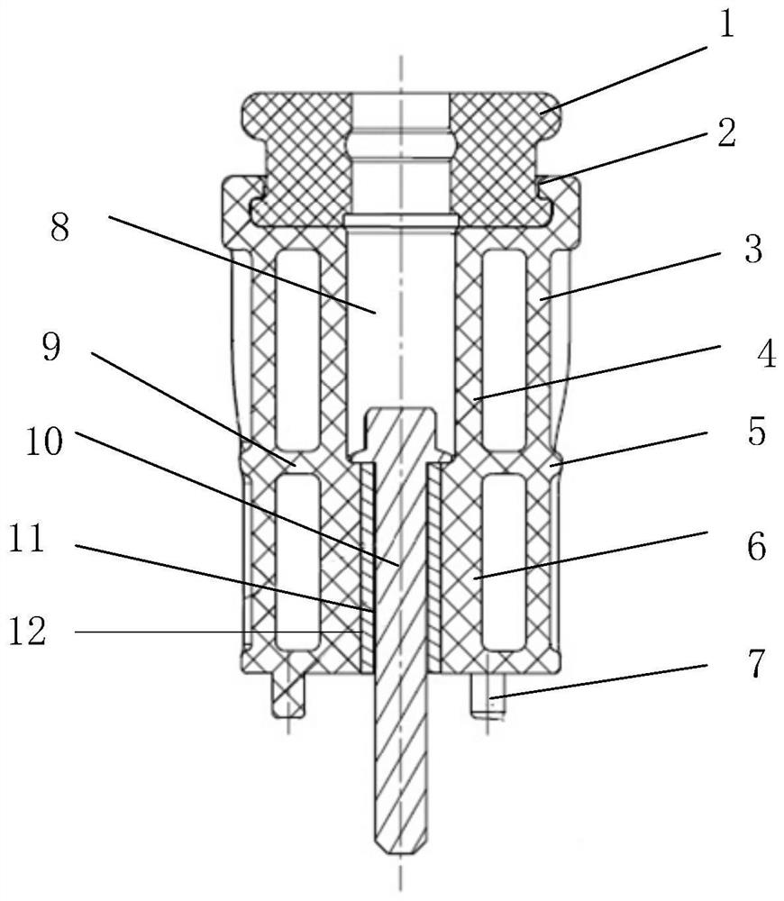
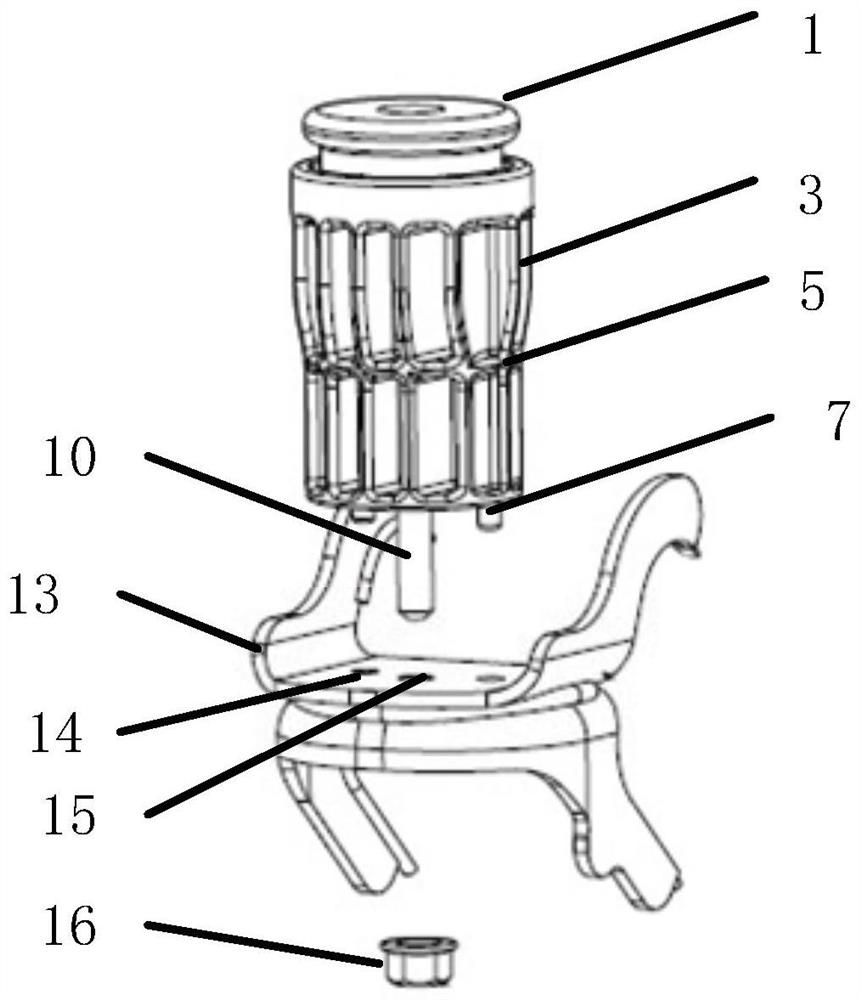
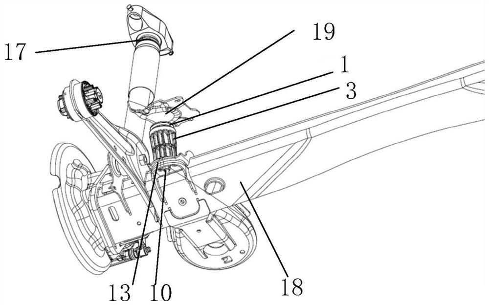
[0039] Example 1, see figure 1 , image 3 As shown, the embodiment of the present invention discloses a torsion beam limiting block structure, which includes:
[0040] The plastic base is provided with a ring-shaped installation part on the upper end, and the inner peripheral side wall of the installation part is provided with installation grooves, and the outer peripheral edge of the lower end of the installation part is provided with twelve outer vertical bars 3 evenly distributed along the circumferential direction, it can be understood that What is more, the quantity of the outer vertical bars 3 can be set according to the required strength and space of the outer vertical bars 3, subject to the actual demand. Each outer vertical bar 3 extends axially downward to the bottom of the plastic base along the axial direction of the plastic base, and the middle parts of two adjacent outer vertical bars 3 pass through the outer circumferential reinforcing rib 5 extending in the ci...
Embodiment 2
[0043] Embodiment 2, continue to refer to figure 1 , on the basis of Embodiment 1, the inner peripheral edge of the lower end of the installation part is also provided with twelve inner vertical bars evenly distributed along the circumferential direction, and the connection line between each inner vertical bar and the outer vertical bar 3 at the corresponding position Falling in the radial direction of the plastic base, the inner vertical bars extend axially downward to the inner peripheral edge of the bottom along the axial direction of the plastic base, and the middle parts of two adjacent inner vertical bars are passed through the Rib connection on the inner circumference.
[0044] Moreover, the connecting point between the outer vertical bar 3 and the outer circumferential reinforcing rib 5 and the connecting point between the inner vertical bar and the inner circumferential reinforcing rib at the corresponding position pass through a radial direction extending radially al...
Embodiment 3
[0045] Embodiment 3, refer to figure 1 , figure 2 , which, on the basis of Example 2, also includes
[0046] The central hole of the limiting block body is a through hole extending along the centerline of the limiting block body 1, the top diameter of the central hole of the limiting block body is smaller than the bottom diameter of the central hole of the limiting block body, and an assembly The hole is used to pass through the fixed tool, and four buckles 2 are evenly distributed in the circumferential direction of the installation groove, which are used to clamp the limit block body 1 installed in the installation groove.
[0047] The first accommodating space 8 is surrounded by the upper section 4 of the inner vertical bar above the inner circumferential reinforcing rib,
[0048] The second accommodating space 12 is surrounded by the lower section 6 of the inner vertical bar located below the inner circumferential reinforcing rib, and the outer diameter of the upper sec...
PUM
 Abstract
Description
Claims
Application Information