Unmanned aerial vehicle landing buffer device

A buffer device, a technology of unmanned aerial vehicles, applied in the field of unmanned aerial vehicles, can solve the problems of the service life of the unmanned aerial vehicle body, the large impact force of the unmanned aerial vehicle, etc., to improve the stability of the fuselage, improve the shock absorption, The effect of broad market promotion prospects

Pending Publication Date: 2020-06-12
青海交通职业技术学院
View PDF6 Cites 2 Cited by
  • Summary
  • Abstract
  • Description
  • Claims
  • Application Information

AI Technical Summary

Problems solved by technology

[0004] The purpose of the present invention is to solve the problem that the unmanned aerial vehicles in the prior art need to land after performing the flight mission, while the existing unmanned aerial vehicles are all rigid landings, and the unmanned aerial vehicles will face a large problem at the moment of landing. impact force, and this impact force will have the disadvantage of affecting the service life of the fuselage of the UAV, and the proposed UAV landing buffer device

Method used


Image

  • Unmanned aerial vehicle landing buffer device
  • Unmanned aerial vehicle landing buffer device
  • Unmanned aerial vehicle landing buffer device

Examples


Embodiment 1

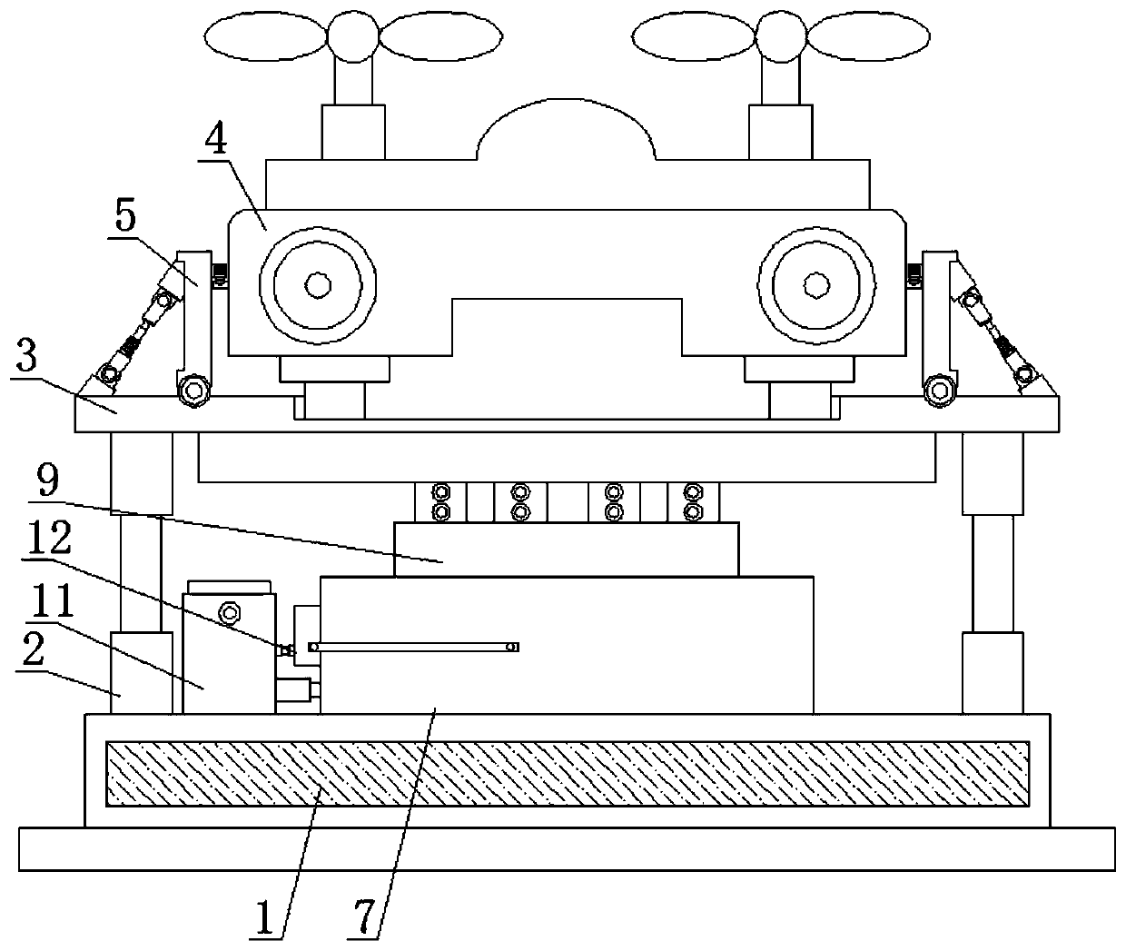
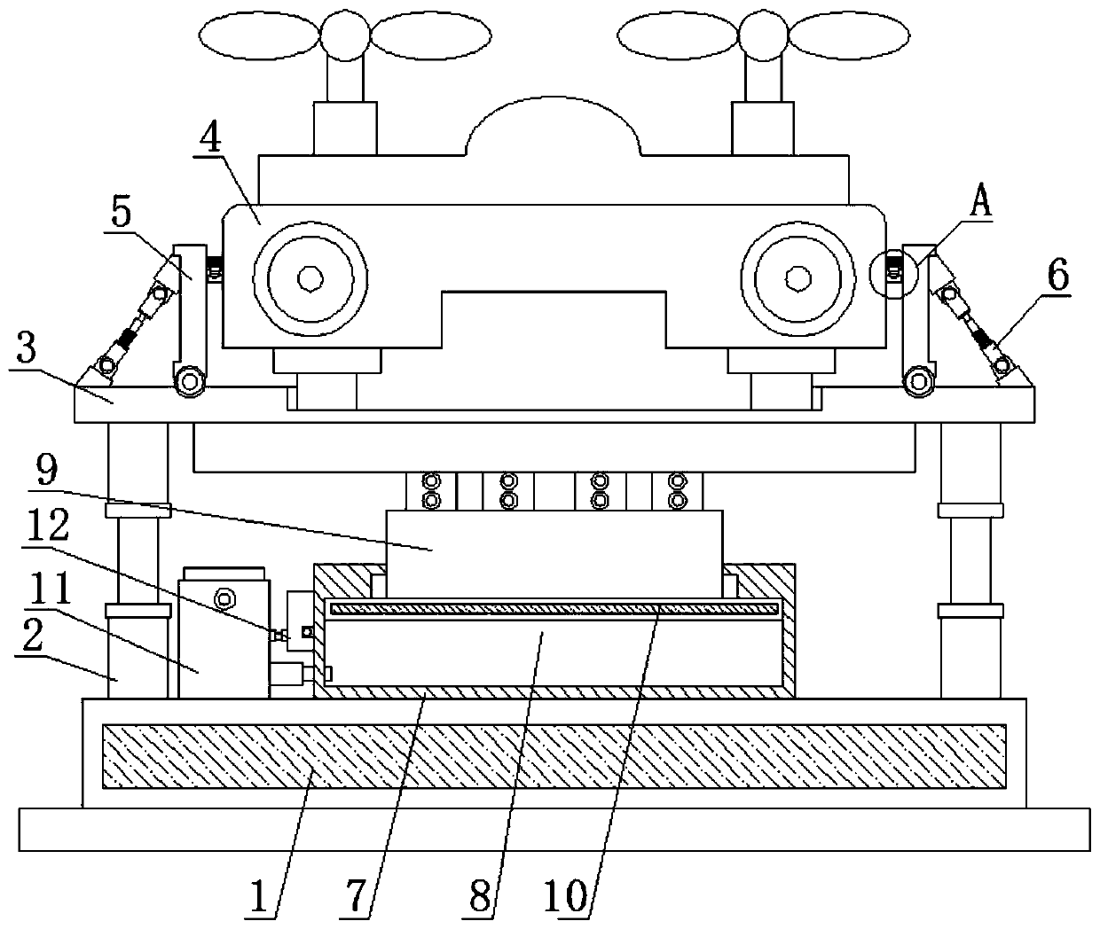
[0028] refer to Figure 1-5 , UAV landing buffer device, including a support base 1, the top of the support base 1 is fixedly installed with two symmetrically arranged buffer rods 2, and the tops of the two buffer rods 2 are fixedly installed with the same landing plate 3, the landing plate 3 A drone 4 is placed on the top of the landing plate 3, and two rotating plates 5 arranged symmetrically are installed on the top of the landing plate 3. The sides of the two rotating plates 5 that are far away from each other are rotatably connected with a push assembly, and the two push assemblies are far away from each other. One side is fixedly connected with the top of the landing plate 3, the both sides of the drone 4 are fixedly equipped with clamping plates 13, and the sides where the two rotating plates 5 are close to each other are fixedly equipped with a deck 14, and the bottom of the deck 14 A sliding groove 15 is provided, and a back-moving spring 16 is fixedly installed on th...

Embodiment 2

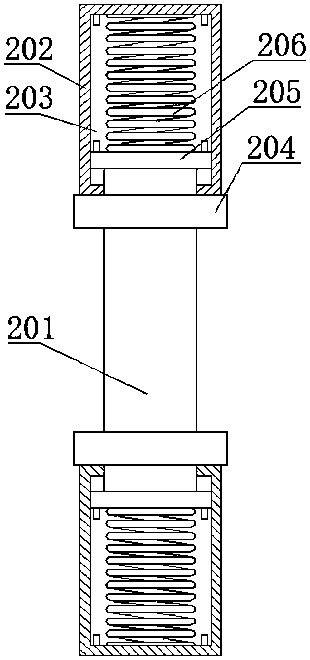
[0030]The buffer rod 2 includes a connecting rod 201, the top and bottom of the connecting rod 201 are slidably connected with a fixing seat 202, and the sides of the two fixing seats 202 close to each other are provided with a limiting groove 203, and the top and bottom ends of the connecting rod 201 respectively extend to A moving plate 205 is fixedly installed in the two limiting grooves 203, and buffer springs 206 are fixedly installed on the sides of the two moving plates 205 away from each other, and the sides of the two buffer springs 206 away from each other are respectively connected to the limiting grooves 203. The inner wall of the far side is fixedly connected. When the landing plate 3 is forced to press the buffer rod 2, the connecting rod 201 will drive the moving plate 205 to move longitudinally in the limit groove 203, which will cause the buffer spring 206 to deform, so the buffer The rod 2 can buffer the landing plate 3 by using the buffer spring 206; The top...


PUM


Abstract

The invention belongs to the technical field of unmanned aerial vehicles, and especially relates to an unmanned aerial vehicle landing buffer device. Aiming at the problems that an existing unmanned aerial vehicle needs to land after executing a flight task, existing unmanned aerial vehicles land rigidly, at the moment of landing, the unmanned aerial vehicle can face large impact force, and the impact force can influence the service life of the fuselage of the unmanned aerial vehicle, the scheme is provided, the unmanned aerial vehicle landing buffer device comprises a supporting base, two symmetrically-arranged buffer rods are fixedly installed at the top of the supporting base, the same landing plate is fixedly installed at the tops of the two buffer rods, an unmanned aerial vehicle is placed at the top of the landing plate, and two symmetrically-arranged rotating plates are rotationally installed at the top of the landing plate. According to the landing buffering device body, soft landing of the unmanned aerial vehicle is achieved, buffering and damping are conducted at the moment when the unmanned aerial vehicle lands on the landing plate, the stability performance of a vehiclebody of the unmanned aerial vehicle is improved, and the wide market popularization prospect is achieved.

Description

technical field [0001] The invention relates to the technical field of drones, in particular to a landing buffer device for drones. Background technique [0002] Unmanned aircraft, referred to as "unmanned aerial vehicle", or "UAV" in English, is an unmanned aircraft that is controlled by radio remote control equipment and its own program control device, or is completely or intermittently operated autonomously by an on-board computer. Drones are often better suited for missions that are too "dumb, dirty or dangerous" than manned aircraft. According to the application field, UAV can be divided into military and civilian. In terms of military use, UAVs are divided into reconnaissance aircraft and target aircraft. In terms of civilian use, drones + industry applications are the real rigid needs of drones; currently, they are used in aerial photography, agriculture, plant protection, micro selfies, express delivery, disaster relief, wildlife observation, infectious disease mon...

Claims


Application Information

Patent Timeline
Patent Type & Authority Applications(China)
IPC IPC(8): B64C25/58B64C25/62B64C27/08
CPCB64C25/58B64C25/62B64C27/08B64U10/10
Inventor 赵文天徐志勇门希华
Owner 青海交通职业技术学院
Why Eureka
Try Eureka