

Novel roof steel truss suspension assembled elevator structure and construction method thereof
A steel truss and prefabricated technology is applied to the new roof steel truss suspended prefabricated elevator structure and its construction field, achieving the effects of good stability, little impact on daily production, and privacy protection
- Summary
- Abstract
- Description
- Claims
- Application Information
AI Technical Summary
Problems solved by technology
Method used
Image

Examples
Embodiment 1
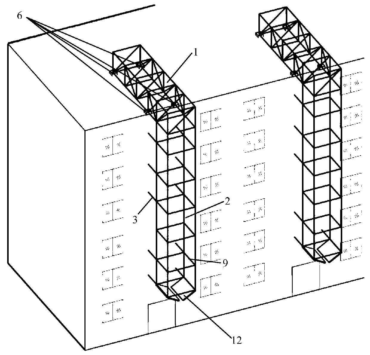
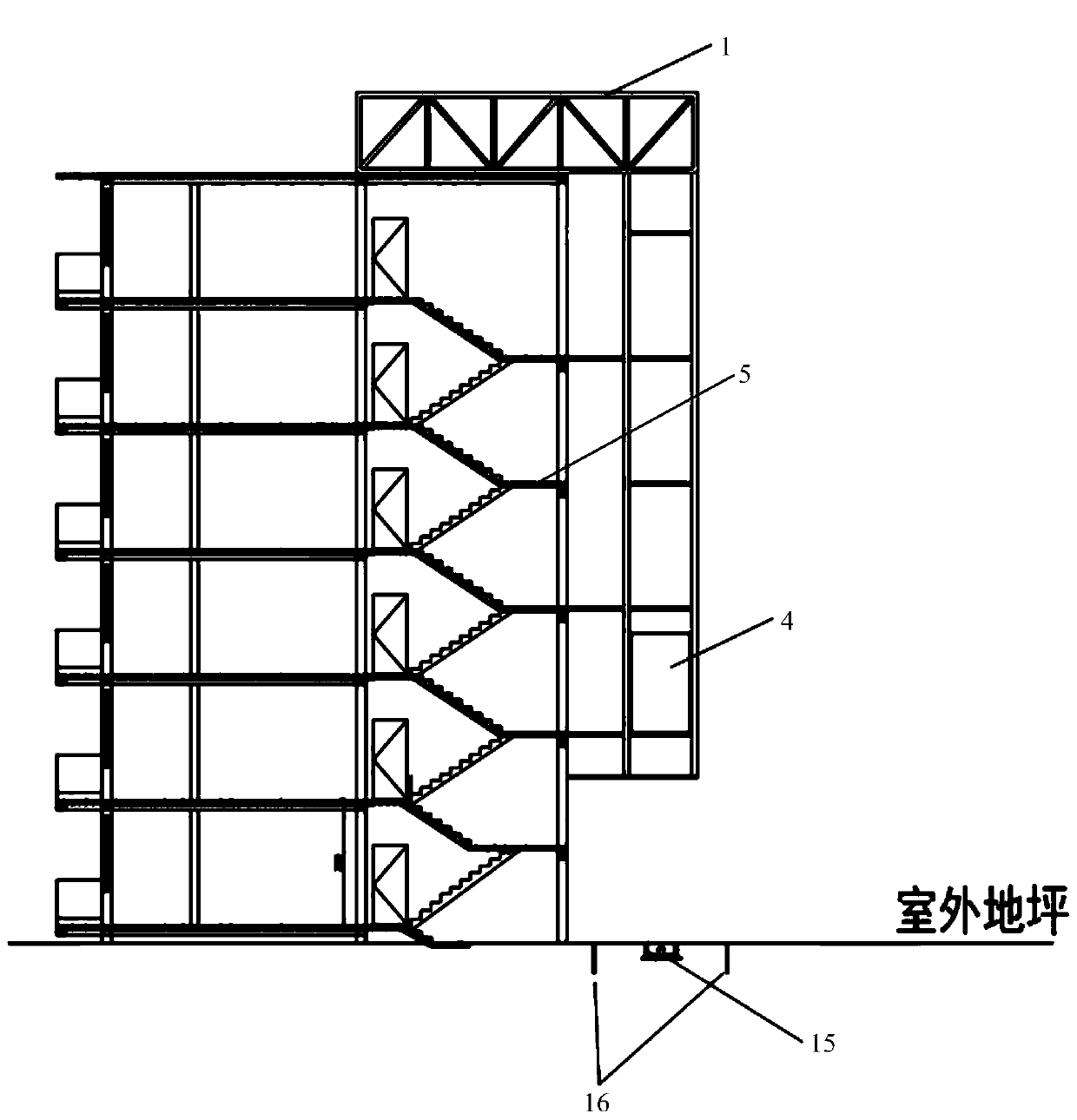
[0074] A new roof steel truss suspension assembled elevator structure, such as Figure 1-3 As shown, including the roof steel truss 1, steel frame well 2 and steel connecting beam 3, the roof steel truss 1, steel frame well 2 and steel connecting beam 3 are all manufactured by the factory, and the steel frame well 2 is suspended on the north side of the original building. Between two adjacent households, on the outside of the original stairwell;
[0075] One end of the roof steel truss 1 is connected to the column or beam of the original building, and the other end is connected to the top of the steel frame shaft 2; there are multiple steel connecting beams 3, except for the bottom and top steel connecting beams 3, the middle steel connecting beams are based on Interlayer setting is required to save materials; one end of each steel connecting beam 3 is connected to the original building, and the other end is connected to the inner side of the column of the steel frame shaft 2 ...
Embodiment 2
[0081] A new roof steel truss suspension assembly type elevator structure, the structure is as shown in Example 1, the difference is that the roof steel truss 1 is welded by section steel, and the connection between the roof steel truss 1 and the column or beam of the original building , and the first end plate 7 is welded at the connection with the steel frame well 2, the second end plate 8 is welded at the connection between the steel frame well 2 and the roof steel truss 1, and the first end plate 8 at one end of the roof steel truss 1 passes through The spherical support 6 is connected to the column or beam of the original building, and the first end plate 7 at the other end of the roof steel truss 1 is connected to the second end plate 8 by bolts, as Figure 4(a) , 4(b) shown.
Embodiment 3
[0083] A novel roof steel truss suspension assembled elevator structure, the structure is as shown in embodiment 2, the difference is, as Figure 5 As shown, the upper seat plate 6.1 of the spherical support 6 is connected to the first end plate 7 at one end of the roof steel truss by bolts, the lower seat plate 6.2 of the spherical support is directly connected to the column or beam of the original building by bolts, and the support of the spherical support Both sides of block 6.3 are embedded in the grooves of upper seat plate 6.1 and lower seat plate 6.2, which can prevent the end of roof steel truss 1 structure from warping, and also have the function of anti-pullout.
[0084] In this embodiment, the spherical bearing adopts the QZ spherical bearing of Hengshui Zhenhai Engineering Rubber Co., Ltd.
PUM
| Property | Measurement | Unit |
|---|---|---|
| Length | aaaaa | aaaaa |
Abstract
Description
Claims
Application Information