
Engine valve rocker arm installation structure

A technology for engine valves and installation structures, which is applied in the direction of engine components, machines/engines, valve devices, etc., and can solve problems such as rocker shaft and rocker arm eccentric wear, failure, and insufficient oil pressure supply

Active Publication Date: 2022-05-24
安徽航瑞航空动力装备有限公司
View PDF31 Cites 0 Cited by
  • Summary
  • Abstract
  • Description
  • Claims
  • Application Information

AI Technical Summary

Problems solved by technology

In the engine with camshaft bottom structure, because the rocker arm and rocker shaft are at the far end of the engine, the oil pressure supply is insufficient, which can only meet the lubrication at the push rod and rocker ball socket, while the rocker arm and rocker shaft move The place is not lubricated, resulting in eccentric wear of the rocker shaft and the rocker arm, and eventually failure

Method used


Image

  • Engine valve rocker arm installation structure
  • Engine valve rocker arm installation structure

Examples


Embodiment Construction

[0016] Below with reference to the accompanying drawings, through the description of the embodiments, the specific embodiments of the present invention will be described in further detail, the purpose is to help those skilled in the art to have a more complete, accurate and in-depth understanding of the concept and technical solutions of the present invention, and contribute to its implementation.

[0017] It should be noted that, in the following embodiments, the “first” and “second” do not represent an absolute distinction relationship in structure and / or function, nor do they represent a sequential execution order, but only for the purpose of Convenience of description.

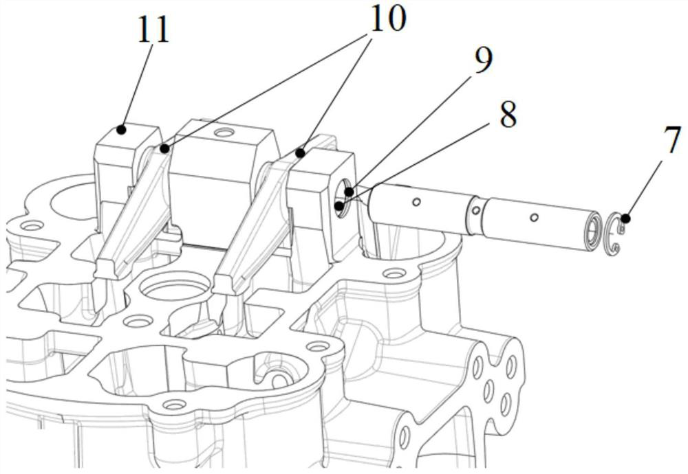
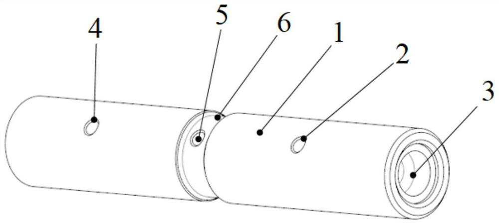
[0018] like figure 1 and figure 2 As shown, the present invention provides an engine valve rocker arm 10 installation structure, including an engine cylinder head 11 and a rocker arm shaft 1, the rocker arm shaft 1 is rotatably arranged on the engine cylinder head 11, and the rocker arm shaft 1 has a fu...


PUM


Abstract

The invention discloses an engine valve rocker arm installation structure, comprising an engine cylinder head and a rocker shaft, the rocker shaft is rotatably arranged on the engine cylinder head, and the rocker shaft has a function for receiving The annular oil groove of the lubricating oil of the cover, the oil inlet hole communicated with the annular oil groove, the axial oil channel communicated with the oil inlet hole, and the first part communicated with the axial oil channel and used to guide the lubricating oil to the first rocker arm installation area An oil outlet hole and a second oil outlet hole communicated with the axial oil passage and used to guide lubricating oil to the second rocker arm installation area, the annular oil groove is located between the first oil outlet hole and the second oil outlet hole, the shaft The oil passage extends axially along the rocker arm shaft, and the first rocker arm installation area and the second rocker arm installation area are used to respectively install a valve rocker arm. The installation structure of the engine valve rocker arm of the present invention satisfies the condition of forming an oil film between the rocker arm shaft and the valve rocker arm, can effectively reduce wear between the rocker arm shaft and the valve rocker arm, and can significantly improve the oil supply efficiency.

Description

technical field [0001] The invention belongs to the technical field of engine parts, and in particular, the invention relates to an engine valve rocker arm mounting structure. Background technique [0002] In the engine with the camshaft bottom structure, the rocker arm shaft is similar to the lever fulcrum, and its main function is to support the rocker arm to open the valve. The traditional rocker arm shaft is fixed by bolts or shaft seats, and the center hole of the rocker arm is connected to the rocker arm shaft. With clearance fit, the rocker arm rotates back and forth at high speed on the rocker arm shaft. The lubrication method between the rocker shaft and the rocker arm is as follows: the oil flows from the oil passage of the cylinder block through the hydraulic tappet and then goes up the center hole of the push rod, and then the oil is supplied from the push rod to the ball socket of the rocker arm. The center hole of the rocker arm is connected, and the oil can b...

Claims


Application Information

Patent Timeline
Patent Type & Authority Patents(China)
IPC IPC(8): F01L1/18F01L1/46F01M9/10
CPCF01L1/181F01L1/46F01M9/10
Inventor 陈旭东刘伟王鸿乐
Owner 安徽航瑞航空动力装备有限公司
Learn More