
Fingerprint sensing device

A sensing device and fingerprint technology, applied in the acquisition/organization of fingerprints/palmprints, instruments, optical fiber light guides, etc., can solve the problems of inability to obtain good image contrast, fingerprint image brightness and fingerprint resolution, and achieve good image quality and small size. volume effect

Pending Publication Date: 2020-06-12
EGIS TECH
View PDF0 Cites 1 Cited by
  • Summary
  • Abstract
  • Description
  • Claims
  • Application Information

AI Technical Summary

Problems solved by technology

[0004] However, the existing optical fingerprint recognition technology is still unable to achieve good image contrast, fingerprint image brightness, and fingerprint resolution in a relatively thin volume. Therefore, how to solve the above problems has become one of the directions for those skilled in the art.

Method used


Image

  • Fingerprint sensing device
  • Fingerprint sensing device
  • Fingerprint sensing device

Examples


Embodiment Construction

[0040] Reference will now be made in detail to the exemplary embodiments of the present invention, examples of which are illustrated in the accompanying drawings. Wherever possible, the same reference numbers are used in the drawings and descriptions to refer to the same or like parts.

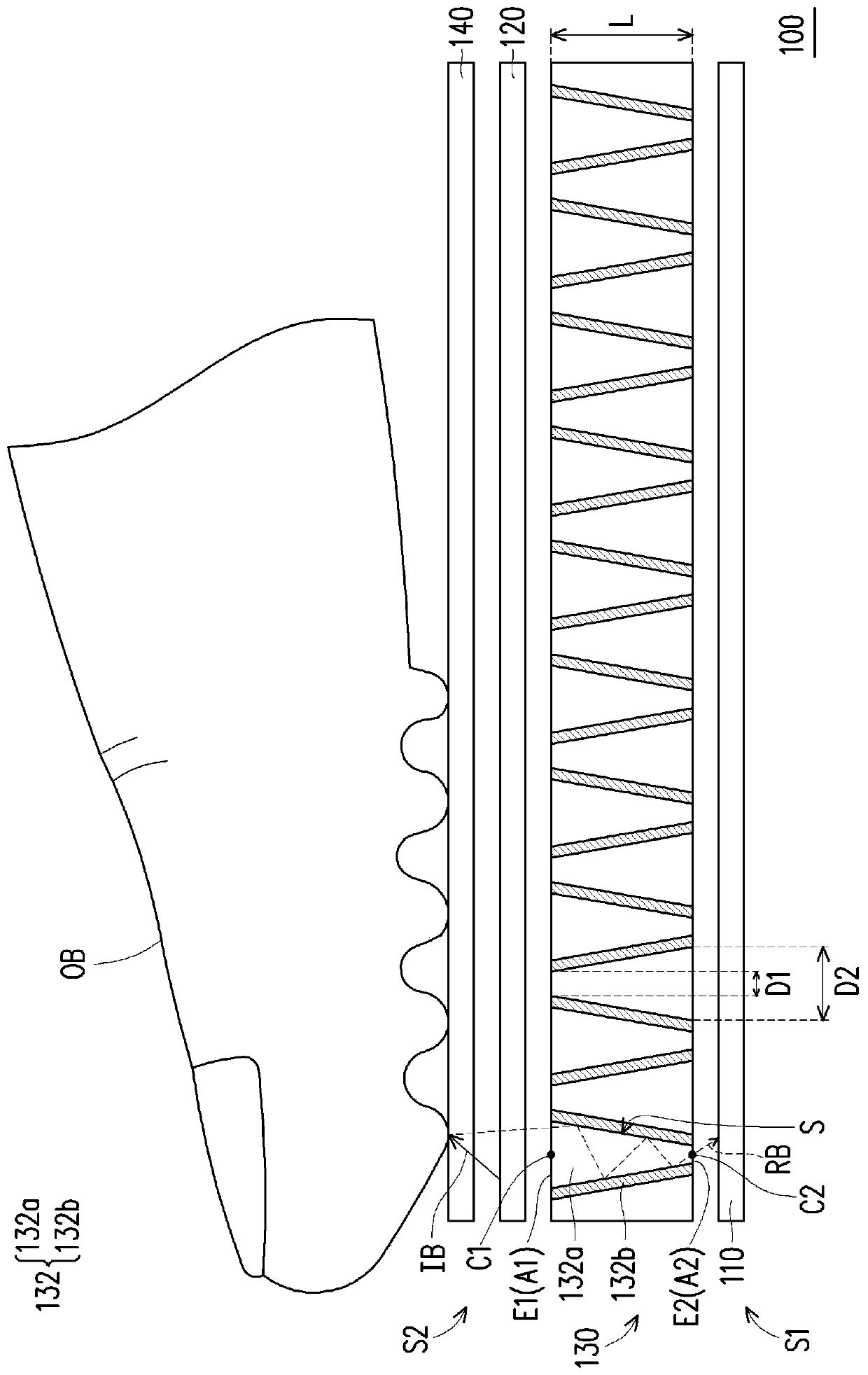
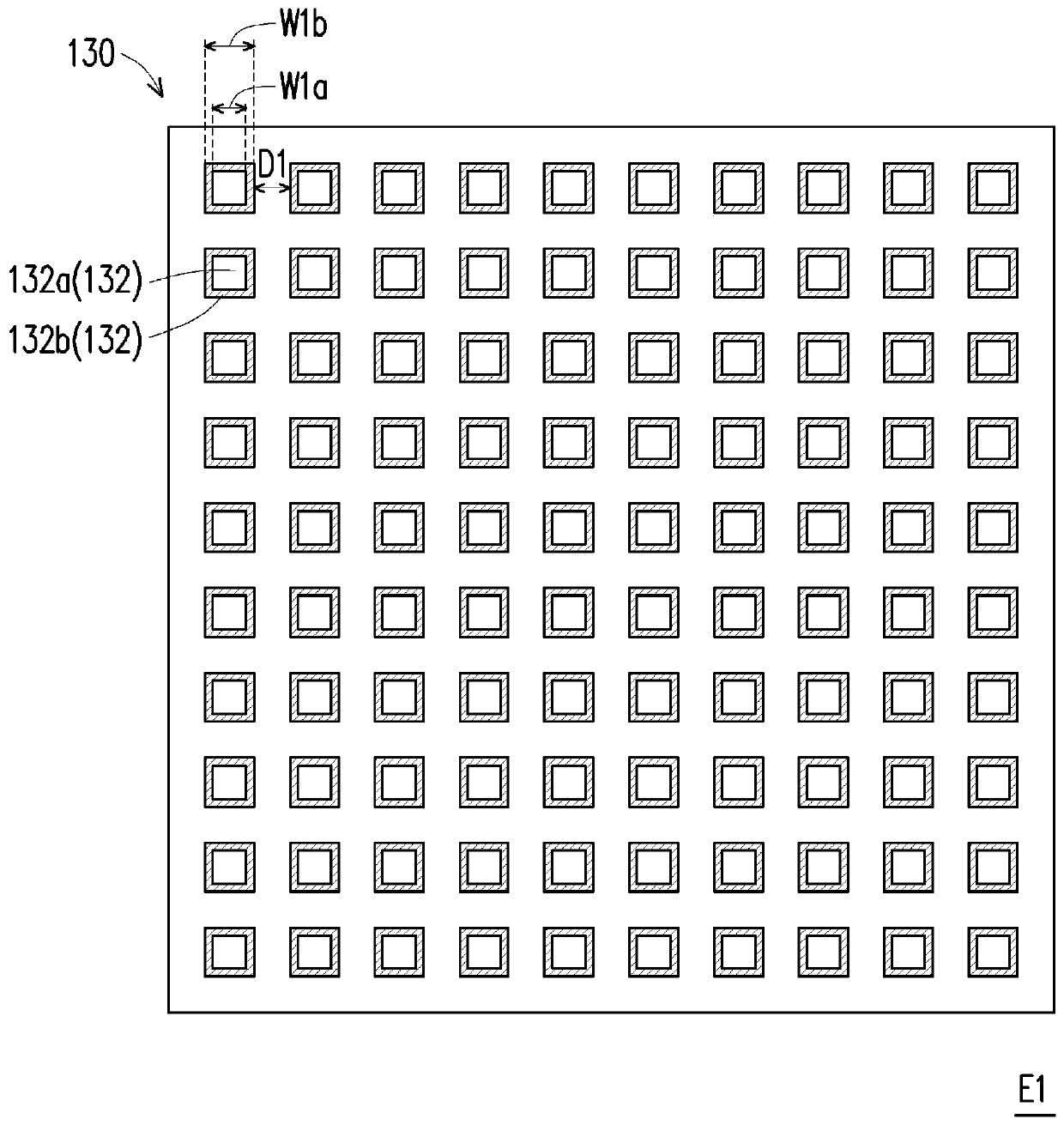
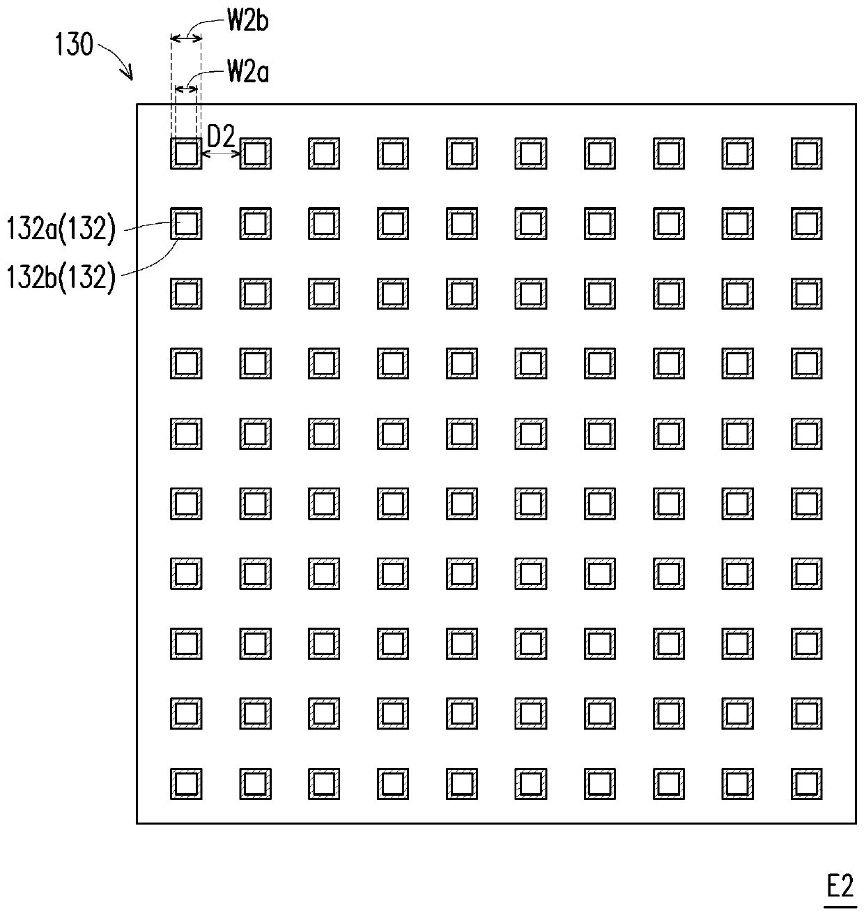
[0041] figure 1 It is a schematic diagram of a fingerprint identification device according to an embodiment of the present invention. Figure 2A for figure 1 Schematic diagram of the top view of the middle light guide plate at the fingerprint side. Figure 2B for figure 1 Schematic diagram of the top view of the light guide plate at the sensing end. image 3 for figure 1 Schematic diagram of the appearance of the core of the optical fiber component.

[0042] Please refer to figure 1 , in this embodiment, the fingerprint identification device 100 includes an image sensor 110 , a light source 120 , a light guide plate 130 and a transparent cover 140 , which are suitable for sensing a user...


PUM


Abstract

The invention provides a fingerprint sensing device, which is suitable for sensing a user's fingerprint and includes an image sensor, a light source and a light guide plate. The image sensor is arranged on the first side of the light guide plate, and the light source is arranged on the second side of the light guide plate. The first side is opposite to the second side. The light guide plate includes a plurality of optical fiber elements, wherein each optical fiber element includes a fingerprint end adjacent to the fingerprint and a sensing end adjacent to the image sensor. The cross-sectionalarea of the core of the optical fiber element decreases from the fingerprint end to the sensing end. The fingerprint sensing device of the present invention can also have good optical quality in a relatively thin volume.

Description

technical field [0001] The invention relates to a fingerprint sensing device. Background technique [0002] As biometric technology matures, many different biometric features are used to identify users. Due to the excellent recognition rate and accuracy of fingerprint recognition technology, it has the widest application level. Among them, optical fingerprint recognition has an advantage in cost, so it is the mainstream of fingerprint recognition technology at this stage. [0003] The principle of the existing optical fingerprint recognition technology is to project light from a light source, and the light is transmitted to the fingerprint through the light guide element, and the fingerprint on the finger reflects the light to be transmitted back to the sensor through the light guide element again, and the sensor Then the fingerprint pattern is sensed according to the reflected light and compared with the fingerprint image stored in the system, so as to achieve the function...

Claims


Application Information

Patent Timeline
Patent Type & Authority Applications(China)
IPC IPC(8): G06K9/00G02B6/00
CPCG02B6/0005G06V40/1318G06V40/1324G02B6/08G06F3/0412G06F3/0421
Inventor 叶肇懿
Owner EGIS TECH
Learn More