Permanent magnet mutual inductance autorotation machine

A permanent magnet and magnet technology, applied in the field of permanent magnet mutual induction autorotation machine, can solve the problems of resource mismatch cost, limitation, consumption of natural resources, etc., and achieve the effect of environmental friendliness, simple device structure and strong operability

Inactive Publication Date: 2020-06-12
王考
View PDF0 Cites 0 Cited by
  • Summary
  • Abstract
  • Description
  • Claims
  • Application Information

AI Technical Summary

Problems solved by technology

[0002] At present, mechanical movement is routinely driven by electric energy, fuel oil, coal, etc., and these direct or indirect energy sources consume natural resources, and the emissions produced in addition cause a greenhouse effect on the environment. How to efficiently reduce emissions and carbon emissions has become an issue in recent years. The research direction of clean energy, although some energy-saving and high-efficiency equipment and methods are currently used, but due to resource mismatch and high cost, it is still restricted in some underdeveloped areas

Method used


Image

  • Permanent magnet mutual inductance autorotation machine
  • Permanent magnet mutual inductance autorotation machine
  • Permanent magnet mutual inductance autorotation machine

Examples


Embodiment 1

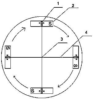
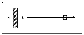
[0025] A permanent magnet mutual induction autorotation machine, a large rectangular magnet with a length of 6 cm, a width of 3 cm and a thickness of 0.3 cm is fixed on a plane so that the S pole is upward. Then place a small magnet with a length of 2 cm, a width of 1 cm, and a thickness of 0.3 cm. The small magnet is a bipolar magnet. Place the left end of the large magnet vertically. The left end of the small magnet is the N pole, and the right end is the S pole. will move from left to right, as attached figure 2 shown.

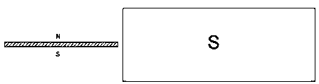
[0026] In order to realize that when the small magnet enters the unipolar magnetic field of the large magnet, the attraction and repulsion between the two are zero, so that the small magnet passes through the unipolar magnetic field without resistance, three conditions must be met. Condition 1, the small magnet enters the unipolar magnetic field of the large magnet without resistance, and it must first be perpendicular to the surface of the unipolar magne...


PUM


Abstract

The invention discloses a permanent magnet mutual inductance autorotation machine. Permanent magnets are processed on a plane according to certain intervals, directions and magnetic poles. A movable mechanical rod is arranged in the center of the plane, small magnets are arranged at the two ends of the mechanical rod respectively, the small magnets are bipolar magnets, the large magnets are singlemagnetic poles, and the small magnets and the permanent magnets in the plane drive the mechanical rod to move through the magnetic mutual inductance effect. The problem that large-pollution energy sources such as electric energy and fuel oil are conventionally used in existing mechanical movement is solved, and the effect of clean energy sources is achieved.

Description

technical field [0001] The invention belongs to the field of machinery and relates to a permanent magnet mutual induction autorotation machine. Background technique [0002] At present, mechanical movement is routinely driven by electric energy, fuel oil, coal, etc., and these direct or indirect energy sources consume natural resources, and the emissions produced in addition cause a greenhouse effect on the environment. How to efficiently reduce emissions and carbon emissions has become an issue in recent years. The research direction of clean energy, although some energy-saving and high-efficiency equipment and methods are currently used, but due to the mismatch of resources and high costs, it is still restricted in some underdeveloped areas. Contents of the invention [0003] In order to solve the above-mentioned deficiencies and shortcomings, the patent of the present invention proposes a permanent magnet mutual induction autorotation machine. [0004] A kind of perman...

Claims


Application Information

Patent Timeline
Patent Type & Authority Applications(China)
IPC IPC(8): H01F7/02
CPCH01F7/0242
Inventor 王考
Owner 王考
Why Eureka
Try Eureka