Distribution transformer grounding structure

A distribution transformer and grounding structure technology, applied in the field of transformers, can solve problems such as easy loosening, affecting normal use, and instability, and achieve the effects of good lightning protection, wide application range, and strong stability

Active Publication Date: 2020-06-12
HONLE ELECTRIC CO LTD
View PDF5 Cites 0 Cited by
  • Summary
  • Abstract
  • Description
  • Claims
  • Application Information

AI Technical Summary

Problems solved by technology

[0003] However, there are still obvious defects in its use: 1. The above-mentioned grounding structure cannot effectively protect against lightning, and the traditional grounding structure of transformers is only a place where lightning arresters are installed randomly. A large amount of inrush current flows on the grounding resistance. When the grounding resistance exceeds the regulations, the arrester cannot operate reliably, and the residual voltage of the arrester is very large, which will act on the high-voltage winding, causing the insulation reduction or breakdown of the high-voltage or low-voltage winding, which poses a safety hazard. ; 2. The above-mentioned device cannot ground the transformer box wall, and the contacts between the components are single connections, which are unstable and easy to loosen, which affects normal use; Jacking up requires setting up extended utility poles, which will not only increase the cumbersome installation and increase the cost, but also the utility poles need to support the overall weight of the transformer. The quality requirements for utility poles on large transformers are high and inconvenient to use

Method used


Image

  • Distribution transformer grounding structure
  • Distribution transformer grounding structure
  • Distribution transformer grounding structure

Examples


Embodiment Construction

[0026] The following will clearly and completely describe the technical solutions in the embodiments of the present invention with reference to the accompanying drawings in the embodiments of the present invention. Obviously, the described embodiments are only some, not all, embodiments of the present invention. Based on the embodiments of the present invention, all other embodiments obtained by persons of ordinary skill in the art without making creative efforts belong to the protection scope of the present invention.

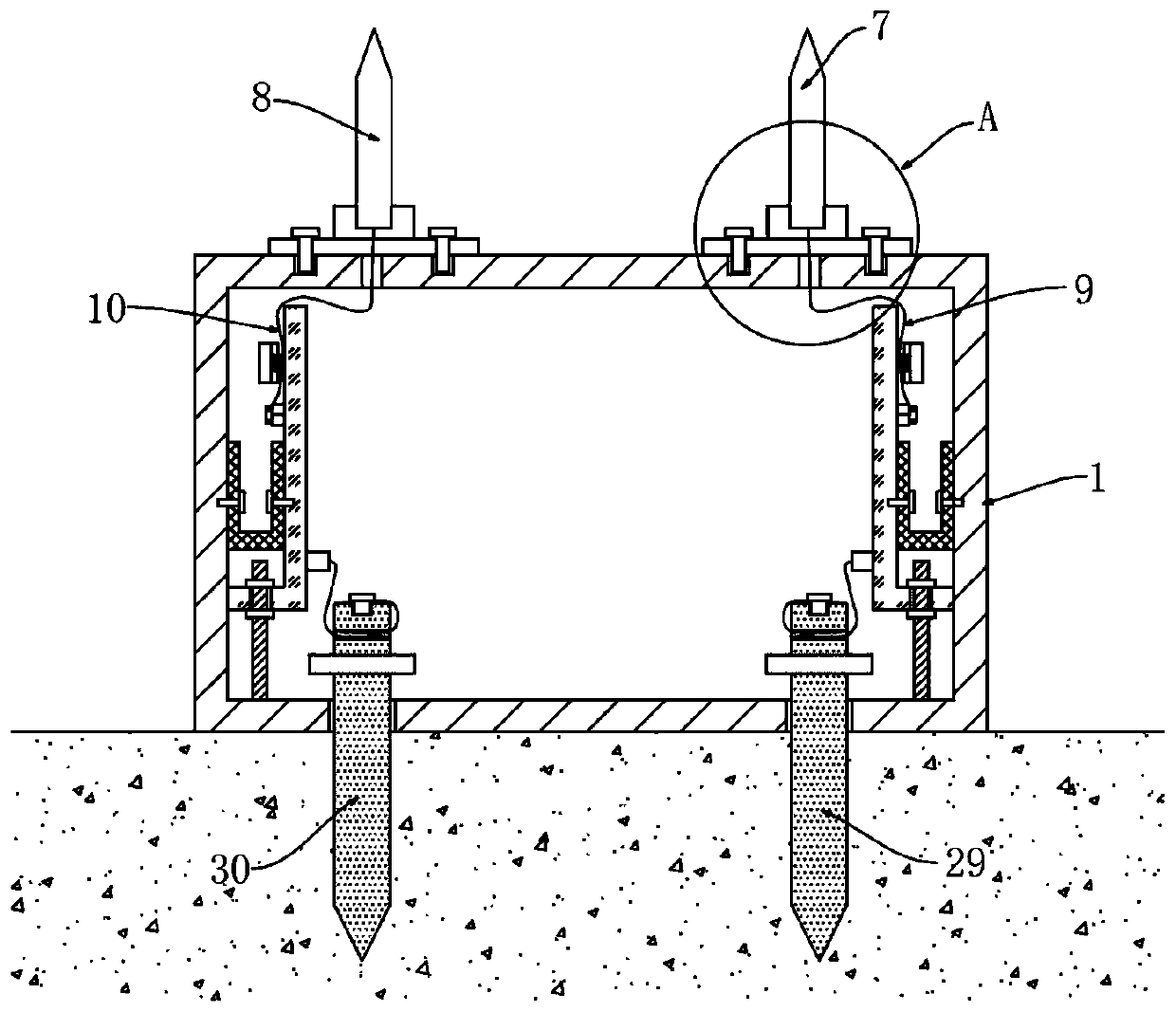
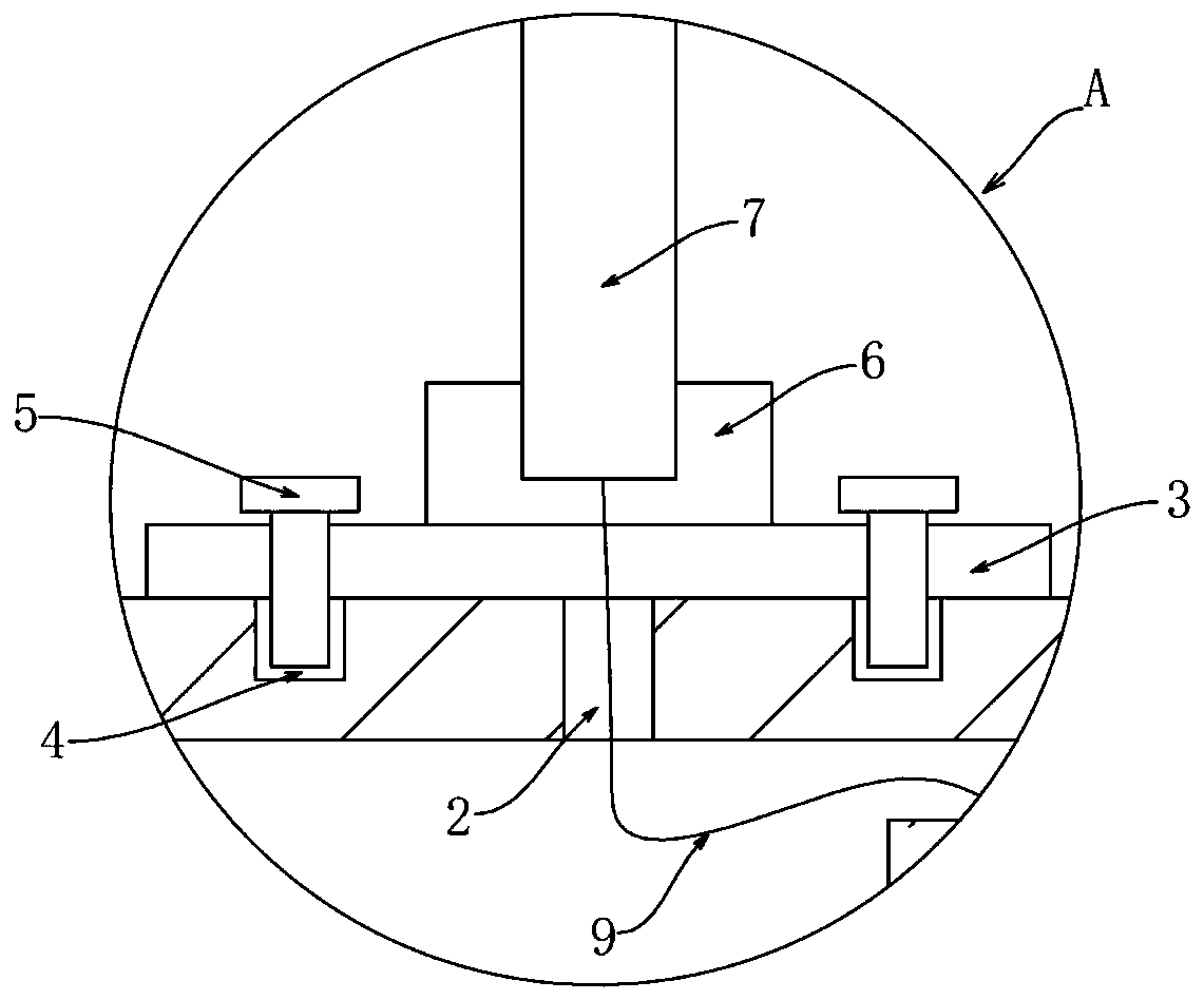
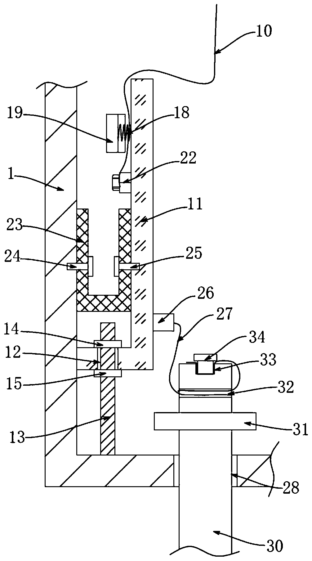
[0027] see Figure 1-4 , the present invention provides a technical solution:

[0028] A distribution transformer grounding structure, comprising a transformer box wall 1, the upper walls of the transformer box wall 1 on the high-voltage side and the low-voltage side are respectively provided with stringing holes 2, and the transformer box wall 1 is respectively provided with bottom plates above the stringing holes 2 3. Blind grooves 4 are arranged symmetrica...


PUM


Abstract

The invention discloses a distribution transformer grounding structure, which comprises a transformer box wall, and is characterized in that the bottom of a high-voltage side lightning arrester is connected with a first lightning protection grounding wire through an electric wire; a groove is formed in the end, away from the through hole, of the iron core flow guide copper bar, a protruding blockis arranged on the side, close to the iron core flow guide copper bar, of the clamping block, and the first lightning protection grounding wire and the second lightning protection grounding wire sequentially pass through the rope penetrating hole and the groove and then are fixed to the wiring screw. A transition copper bar is clamped between the iron core flow guide copper bar and the transformerbox wall, and a gathering binding post is arranged on the iron core flow guide copper bar. The ends, located in the inner cavity of the transformer box wall, of the high-voltage side grounding columnand the low-voltage side grounding column are each provided with a wiring annular groove. According to the distribution transformer grounding structure, the position and the connection mode of the lightning arrester are reasonably arranged, effective lightning protection is achieved, the grounding column is convenient to install, the internal structure can be detached and replaced independently,the requirement for stable connection after installation and clamping can be met, and the distribution transformer grounding structure is quite worthy of popularization.

Description

technical field [0001] The invention relates to the technical field of transformers, in particular to a grounding structure of a power distribution transformer. Background technique [0002] In the prior art, a superconducting transformer grounding structure with the application number "201720726906.0" includes a utility pole, the inner side of the middle position of the utility pole is connected with a support plate by bolts, and a superconducting transformer is welded on the top of the support plate The shell, both sides of the bottom inner wall of the superconducting transformer shell are welded with winding posts, the outer wall of the winding post is wound with superconducting transformer coils, and the bottom inner wall of the superconducting transformer shell is welded with the first A terminal, the bottom of the support plate is welded with a connecting rod, the end of the connecting rod away from the support plate is sleeved with a connecting ring, the outer wall of...

Claims


Application Information

Patent Timeline
Patent Type & Authority Applications(China)
IPC IPC(8): H01F27/28H01F27/40H01F27/02H01R4/66
CPCH01F27/02H01F27/28H01F27/402H01F41/00H01R4/66
Inventor 沈文齐沈梦然
Owner HONLE ELECTRIC CO LTD
Why Eureka
Try Eureka