A method for automatically measuring the propagation delay of an irig-b timing signal, a timing slave station and a timing system

A technology for signal propagation and automatic measurement, applied in transmission systems, time-division multiplexing systems, multiplexing communications, etc., can solve problems such as manual measurement of propagation delay, facilitate practical promotion and application, and reduce technical requirements Good level and compatibility

Active Publication Date: 2022-06-17
CHENGDUSCEON ELECTRONICS
View PDF4 Cites 0 Cited by
  • Summary
  • Abstract
  • Description
  • Claims
  • Application Information

AI Technical Summary

Problems solved by technology

[0003] In order to solve the cumbersome problem of manual measurement and input of the propagation delay existing in the existing IRIG-B (DC) timing system, the purpose of the present invention is to provide a method for automatically measuring the propagation delay of the IRIG-B timing signal, and the timing from station and timing system

Method used


Image

  • A method for automatically measuring the propagation delay of an irig-b timing signal, a timing slave station and a timing system
  • A method for automatically measuring the propagation delay of an irig-b timing signal, a timing slave station and a timing system
  • A method for automatically measuring the propagation delay of an irig-b timing signal, a timing slave station and a timing system

Examples


Embodiment 1

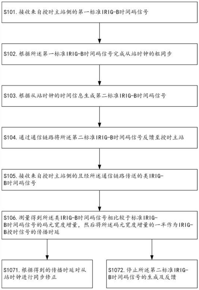
[0051] like Figures 1 to 3 As shown, the method for automatically measuring the propagation delay of an IRIG-B timing signal provided in this embodiment may, but is not limited to, include the following steps S101 to S106.

[0052] S101. Receive a first standard IRIG-B time code signal from the timing master station side, wherein the first standard IRIG-B time code signal is generated on the timing master station side according to the time information of the master station clock.

[0053] In the step S101, the first standard IRIG-B time code signal is a standard IRIG-B (DC) serial time code signal, and the generation method is an existing conventional method.

[0054] S102. Complete the coarse synchronization of the slave station clocks according to the first standard IRIG-B time code signal.

[0055] In the step S102, the method of performing coarse synchronization is the existing conventional time synchronization method, which may be but not limited to the following steps:...

Embodiment 2

[0072] like Figure 4As shown, based on the technology of the first embodiment, this embodiment provides a timing slave station for implementing the method described in the first embodiment, including a signal transceiver unit, a coarse synchronization processing unit, a signal generation unit, and a delay measurement unit unit; on the one hand, the signal transceiver unit is used to receive the first standard IRIG-B time code signal and IRIG-B-like time code signal from the timing master station side, and on the other hand, it is used to feed back to the timing master station through the communication link The second standard IRIG-B time code signal, wherein the first standard IRIG-B time code signal is generated on the side of the timing master station according to the time information of the master station clock, and the second standard IRIG-B time code signal is generated according to the time information of the master station clock. The first standard IRIG-B time code sig...

Embodiment 3

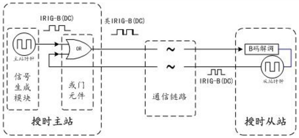
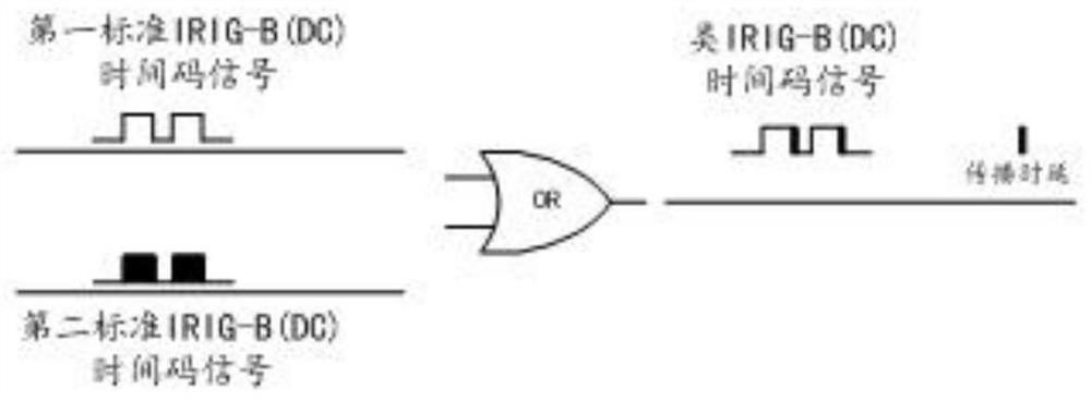
[0076] like Figure 5 As shown, this embodiment further provides a timing system based on the technology of the second embodiment, including a timing master station and a timing slave station as described in the second embodiment, wherein the timing master station includes a signal generation module an OR gate element; the signal generation module is configured to generate a first standard IRIG-B time code signal according to the time information of the master clock, and transmit the first standard IRIG-B time code signal to the OR gate element The first input end of the OR gate element; the second input end and the output end of the OR gate element are respectively connected to the signal transceiver unit of the timing slave station through the same communication link.

[0077] Preferably, the signal generation module is further configured to stop the generation of the first standard IRIG-B time code signal when it is found that the second input end of the OR gate element is ...


PUM


Abstract

The invention relates to the technical field of time synchronization, and discloses a method for automatically measuring the propagation delay of IRIG-B timing signals, a timing slave station and a timing system, that is, the slave station clock is roughly synchronized on the side of the timing slave station, and then based on the coarse The synchronization result feeds back the standard IRIG-B time code signal to the timing master station, and finally obtains the propagation delay of the IRIG-B timing signal based on the "OR" logic processing signal obtained from the master-slave standard IRIG-B time code signal, so that The timing slave station can automatically measure the time delay information for further precise synchronization. At the same time, the whole measurement process does not require manual participation, which can avoid human error, ensure measurement accuracy, and reduce the technical requirements of equipment for maintenance personnel.

Description

technical field [0001] The invention belongs to the technical field of time synchronization, and in particular relates to a method for automatically measuring the propagation delay of an IRIG-B timing signal, a timing slave station and a timing system. Background technique [0002] In the traditional time synchronization technology, IRIG-B(DC) (referred to as B code) is a serial time code formulated by the TelecommunicaTIon Group to which IRIG belongs. It is used for time synchronization of each system. Its frame length is 1s, including 100 symbols; it is coded by pulse width modulation, and there are three width symbols, representing "0", "1" and "P" respectively; in addition, DC in parentheses indicates that the IRIG-B time code signal adopts DC square. In the timing system (wave signal method), if high-precision time synchronization is required, it is necessary to manually calibrate the propagation delay between the timing master and slave stations, and other testing inst...

Claims


Application Information

Patent Timeline
Patent Type & Authority Patents(China)
IPC IPC(8): H04L43/0852H04J3/06
CPCH04L43/0852H04J3/0635
Inventor 熊嘉明许俊董道鹏章巍
Owner CHENGDUSCEON ELECTRONICS
Why Eureka
Try Eureka