
Micro-groove jet polishing device and polishing method

A polishing device and micro-groove technology, which is applied to used abrasive processing devices, abrasive jet machine tools, abrasives, etc., can solve the problems of limiting the application of micro-groove structures, high processing efficiency, and complex equipment costs, etc., to achieve easy Automated processing, low production cost, and improved surface quality

Pending Publication Date: 2020-12-15
TIANJIN UNIV
View PDF0 Cites 1 Cited by
  • Summary
  • Abstract
  • Description
  • Claims
  • Application Information

AI Technical Summary

Problems solved by technology

The main problems of the above-mentioned methods of processing micro-grooves are poor surface quality, complex equipment, high cost and low processing efficiency, which limit the application of micro-groove structures. Therefore, a suitable micro-groove polishing method and device are needed

Method used


Image

  • Micro-groove jet polishing device and polishing method
  • Micro-groove jet polishing device and polishing method
  • Micro-groove jet polishing device and polishing method

Examples


Embodiment 1

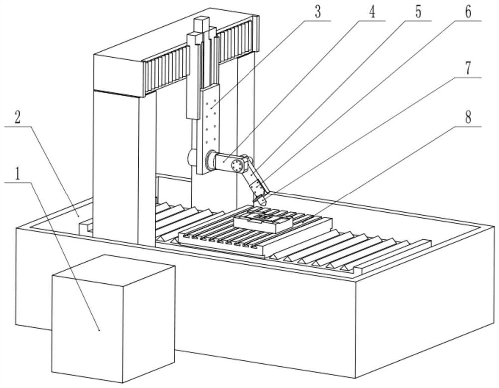
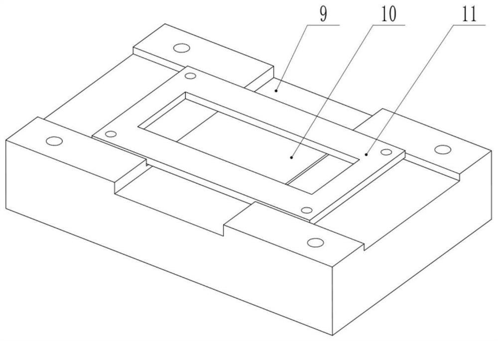
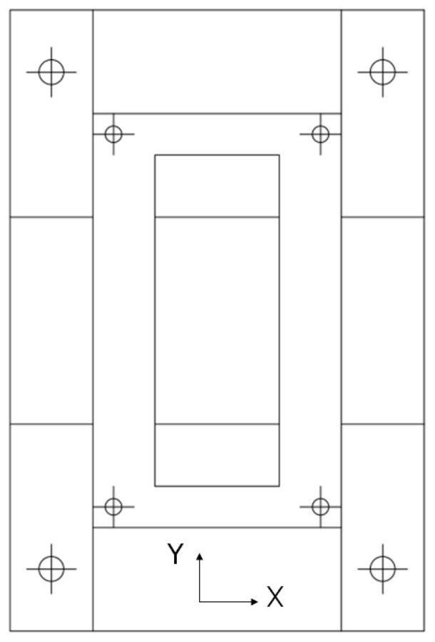
[0046] like figure 1 As shown, a micro-groove jet polishing device includes a base 2, a liquid supply system 1, a polishing nozzle 7 and a worktable 8, and a side wall of the base 2 is provided with the liquid supply system 1. The liquid supply system 1 is used to deliver the polishing liquid containing abrasive particles to the polishing nozzle so as to impact the micro-grooves to be polished. Wherein, the abrasive particles in the polishing liquid interact with the workpiece for nano-removal, so as to realize polishing micro-grooves; the liquid supply system 1 transports the configured polishing liquid to the Polishing nozzle 7. A five-axis motion platform is fixedly installed on the base 2 for adjusting the posture of the polishing nozzle relative to the workpiece to be processed, including a three-axis linear motion mechanism and a two-axis rotary motion mechanism. The polishing nozzle 7 is installed at the end of the five-axis motion platform. The three-axis linear mot...

Embodiment 2

[0057] This embodiment is basically the same as Embodiment 1, except that the cover plate 11 is replaced with the mask 12 . like figure 1 , Figure 5 As shown in -7, the micro-groove jet polishing device of the present invention includes a base 2, a liquid supply system 1, a polishing nozzle 7 and a worktable 8, and a mask 12 for polishing the micro-groove.

[0058] Figure 5 -7 shows a schematic diagram of the mask 12 fixing the workpiece, and its ends are correspondingly provided with holes for riveting with the object table 9 , the mask 12 is pressed on the workpiece, and then riveted with the object table 9 . The mask 12 has grooves, and the width of the bottom of the grooves of the mask is the same as the width of the micro-grooves to be polished. As shown in FIG. 7 , the groove sidewall of the mask has an inclination angle of 45°, and the sidewall of the mask groove can control the polishing liquid jet ejected by the polishing nozzle 4 along the mask groove on the sur...


PUM

PropertyMeasurementUnit
angleaaaaaaaaaa

Abstract

The invention discloses a micro-groove jet polishing device and a polishing method. The polishing device comprises a base, a liquid supply system, polishing nozzles and a workbench, wherein a workpiece fixing assembly is detachably mounted on the upper surface of the workbench and used for placing a to-be-machined workpiece; the workpiece fixing assembly is correspondingly arranged below the polishing nozzles; the workpiece fixing assembly comprises a storage table and a fixing element; the storage table is placed on the upper surface of the workbench; a first groove and a second groove whichare vertically arranged are formed in the upper surface of the storage table; the vertical depth of the first groove is greater than that of the second groove; the polishing nozzles comprise a millimeter-scale polishing nozzle and a micron-scale polishing nozzle; the fixing element comprises a cover plate and a mask; when the polishing nozzles are the micron-scale polishing nozzle, the fixing element is the cover plate; and when the polishing nozzles are the millimeter-scale polishing nozzle, the fixing element is the mask.

Description

technical field [0001] The invention belongs to the field of microstructure processing, and in particular relates to a microgroove jet polishing device and a polishing method. Background technique [0002] In recent years, with the development of science and technology, products have gradually developed in the direction of precision, integration and high performance. Parts with micro-grooved structure features have been widely used in many fields, including optics, chemistry, biomedicine, Microelectronics, etc. For example, the optical glass microgrooved array has the functions of reducing light reflectivity, improving transmittance and diffraction efficiency, and controlling light energy distribution; in cell research, it is necessary to use glass devices with microgrooves to simulate the microenvironment of cells. The differentiation, growth and migration of cells; the electrode plates of fuel cells, the friction and drag reduction devices on fluid machines, the grating c...

Claims


Application Information

Patent Timeline
Patent Type & Authority Applications(China)
IPC IPC(8): B24C1/08B24C9/00B24C3/04
CPCB24C1/08B24C3/04B24C9/00
Inventor 曹中臣闫升亲李世鹏姜向敏张军鹏
Owner TIANJIN UNIV
Learn More