Method for automatically measuring IRIG-B time service signal propagation time delay, time service slave station and time service system
A technology for signal propagation and automatic measurement, applied in transmission systems, digital transmission systems, time-division multiplexing systems, etc., can solve problems such as manual measurement of propagation time delay, achieve practical promotion and application, reduce technical requirements, The effect of reducing workload
- Summary
- Abstract
- Description
- Claims
- Application Information
AI Technical Summary
Problems solved by technology
Method used
Image
Examples
Embodiment 1
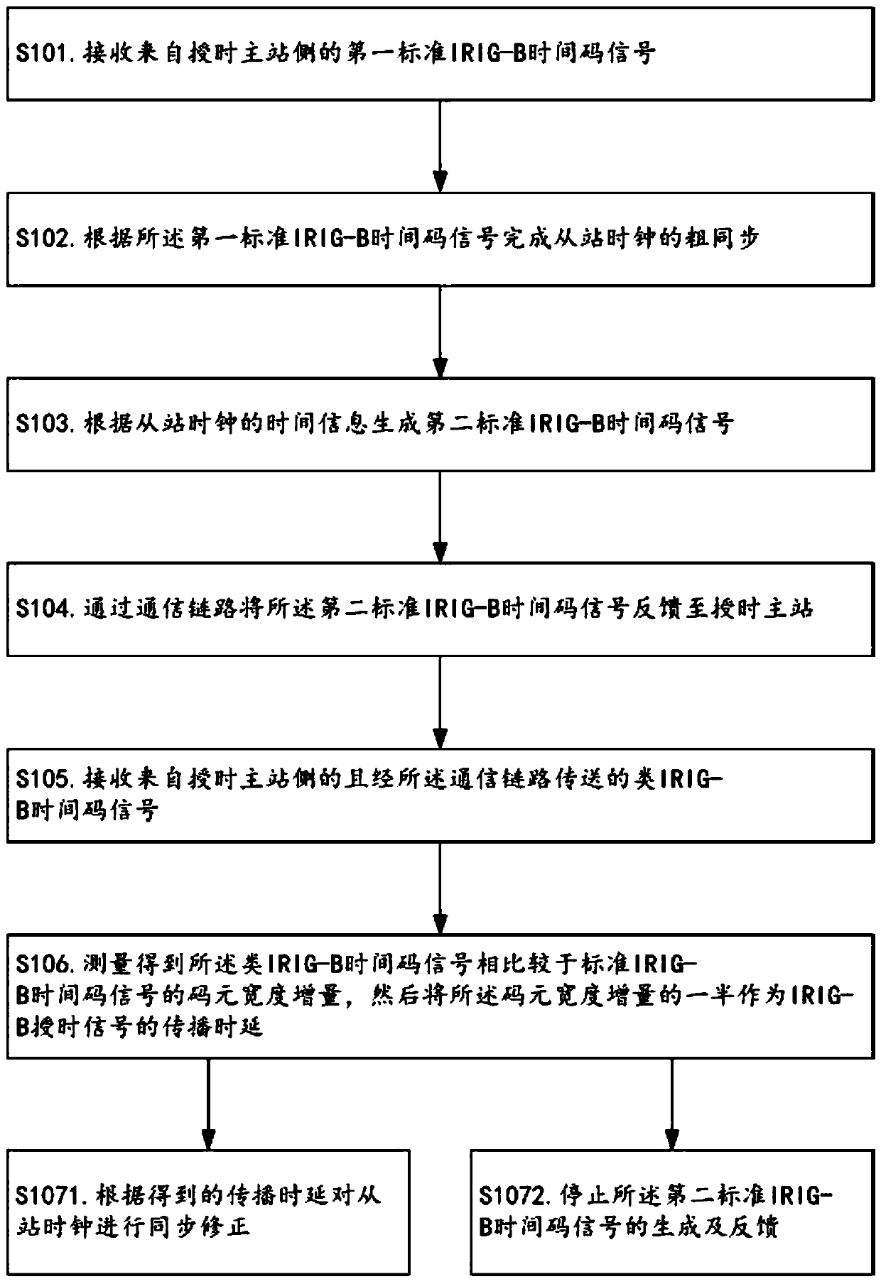
[0051] Such as Figure 1~3 As shown, the method for automatically measuring the propagation delay of the IRIG-B timing signal provided in this embodiment may, but is not limited to, include the following steps S101-S106.
[0052] S101. Receive the first standard IRIG-B time code signal from the time service master station side, wherein the first standard IRIG-B time code signal is generated on the time service master station side according to the time information of the master station clock.
[0053] In the step S101, the first standard IRIG-B time code signal is a standard IRIG-B (DC) serial time code signal, and its generation method is an existing conventional method.
[0054] S102. Complete the coarse synchronization of the clocks of the slave stations according to the first standard IRIG-B time code signal.
[0055] In the step S102, the coarse synchronization method is an existing conventional time synchronization method, which may be, but not limited to, the following ...
Embodiment 2
[0072] Such as Figure 4As shown, on the basis of the technology in Embodiment 1, this embodiment provides a timing slave station for implementing the method described in Embodiment 1, including a signal transceiver unit, a coarse synchronization processing unit, a signal generation unit, and a delay measurement Unit; the signal transceiving unit is used to receive the first standard IRIG-B time code signal and the class IRIG-B time code signal from the time service master station side on the one hand, and is used to feed back to the time service master station through a communication link on the other hand The second standard IRIG-B time code signal, wherein, the first standard IRIG-B time code signal is generated at the time service master station side according to the time information of the master station clock, and the second standard IRIG-B time code signal is generated according to the time information of the master station clock The first standard IRIG-B time code sign...
Embodiment 3
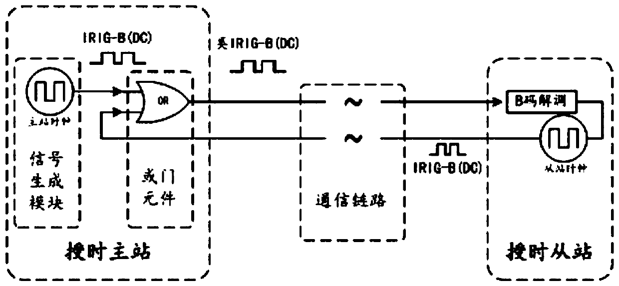
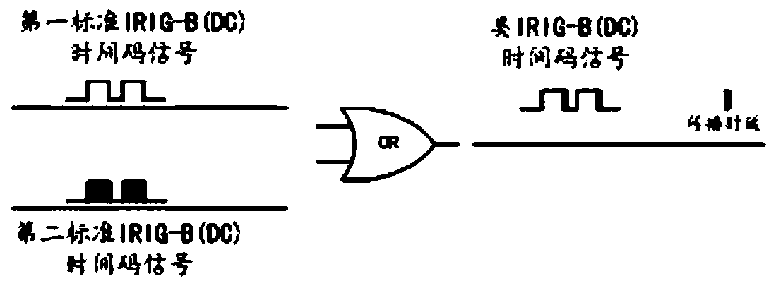
[0076] Such as Figure 5 As shown, this embodiment also provides a timing system based on the technology of Embodiment 2, including a timing master station and a timing slave station as described in Embodiment 2, wherein the timing master station includes a signal generating module AND OR gate element; the signal generation module is used to generate the first standard IRIG-B time code signal according to the time information of the master station clock, and transmit the first standard IRIG-B time code signal to the OR gate element The first input end of the OR gate element; the second input end and output end of the OR gate element are respectively connected to the signal transceiving unit of the timing slave station through the same communication link.
[0077] Optimally, the signal generation module is also used to stop the generation of the first standard IRIG-B time code signal when it is found that the second input terminal of the OR gate element is switched from a signa...
PUM
 Abstract
Description
Claims
Application Information
 - R&D
- Intellectual Property
- Life Sciences
- Materials
- Tech Scout
- Unparalleled Data Quality
- Higher Quality Content
- 60% Fewer Hallucinations
Browse by: Latest US Patents, China's latest patents, Technical Efficacy Thesaurus, Application Domain, Technology Topic, Popular Technical Reports.
© 2025 PatSnap. All rights reserved.Legal|Privacy policy|Modern Slavery Act Transparency Statement|Sitemap|About US| Contact US: help@patsnap.com


