
Powder processing device

A processing device and powder technology, applied in grain processing and other directions, to achieve the effect of a simple structure

Active Publication Date: 2021-10-19
HOSOKAWA MICRON CORP
View PDF14 Cites 0 Cited by
  • Summary
  • Abstract
  • Description
  • Claims
  • Application Information

AI Technical Summary

Problems solved by technology

The airflow colliding with the fins flows upwards and downwards

Method used


Image

  • Powder processing device
  • Powder processing device
  • Powder processing device

Examples


Embodiment Construction

[0037] The powder processing apparatus according to the present invention will be described with reference to the drawings.

[0038]

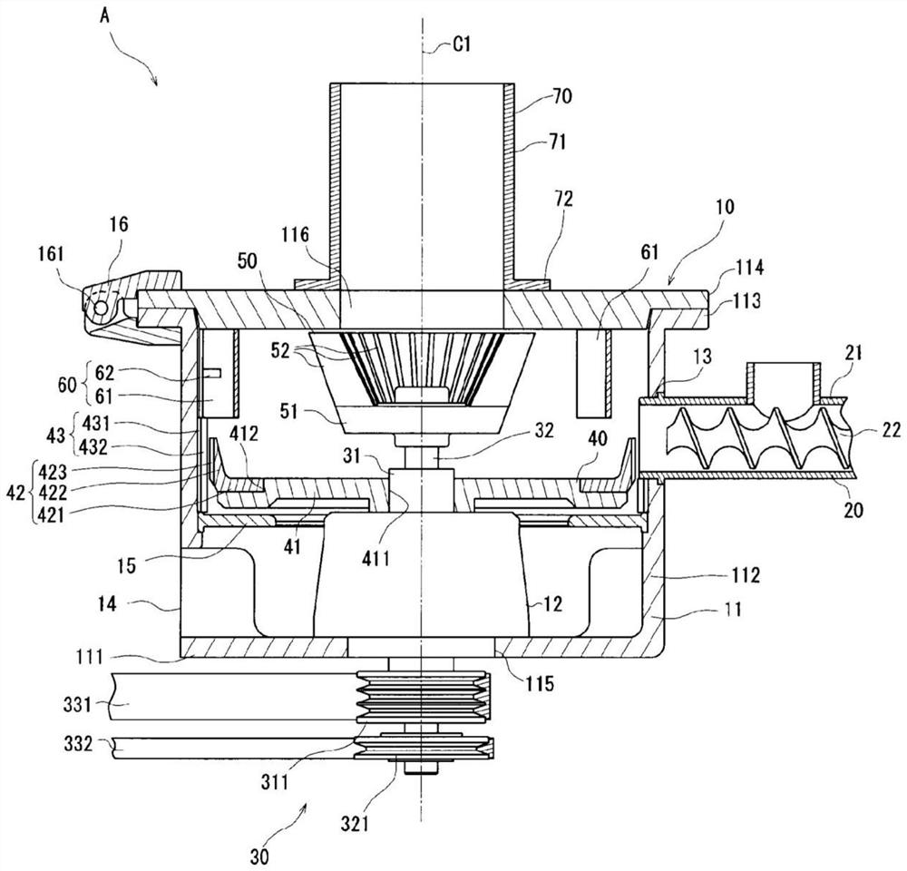
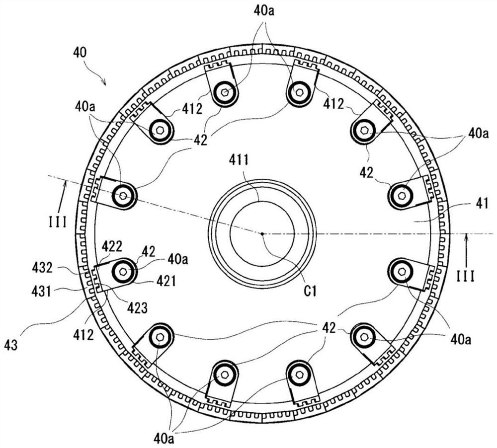
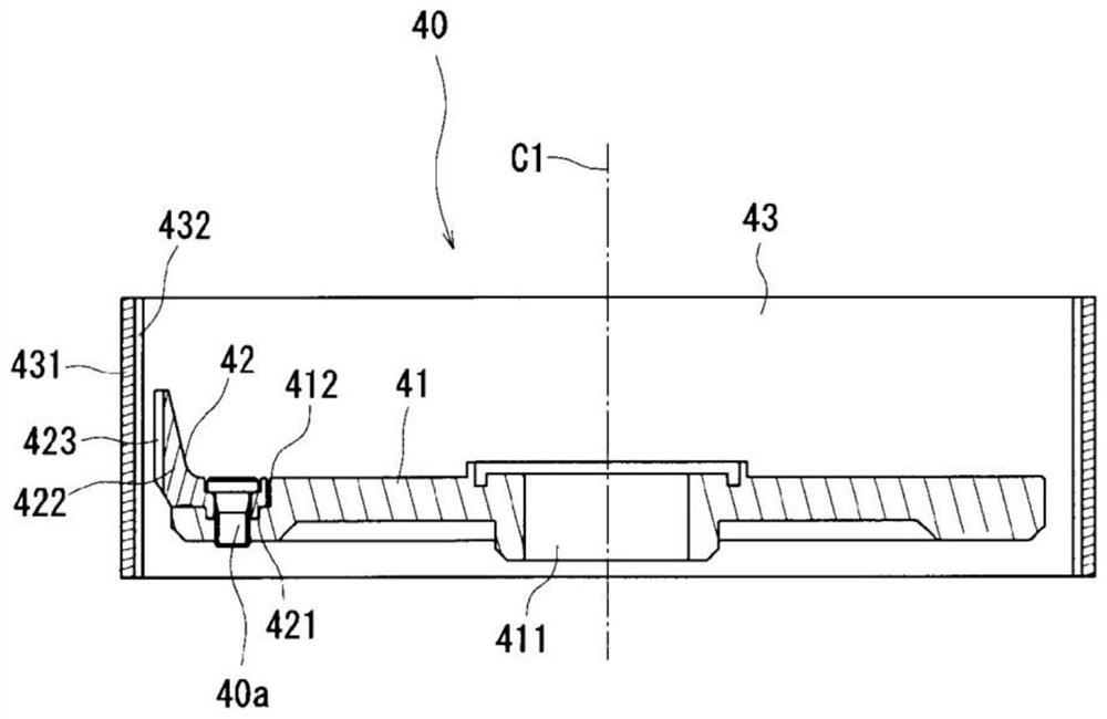
[0039] figure 1 It is a cross-sectional view of the powder processing device according to the present invention. The powder processing device A crushes the bulk material into powder or granules. Such as figure 1 As shown, the powder processing apparatus A includes a frame body 10 , a raw material supply unit 20 , a drive unit 30 , a pulverization unit 40 , a swirling air flow generation unit 50 , a guide unit 60 and an air flow outflow unit 70 . In addition, let the direction in which the central axis C1 extends be an up-down direction. The direction perpendicular to the up-down direction is defined as a radial direction, the side toward the center is defined as the inner side, and the side away from the center is defined as the outer side. In addition, let the direction along the circumference centered on the central axis C1 be the circu...


PUM


Abstract

In order to achieve low flow rate of air flow and miniaturization of powder and granules with a simple structure, the powder processing device also includes a cylindrical frame, a raw material supply part, a first rotating body that rotates around the central axis, and pulverizes the raw material into powder. Granular pulverizing means, a second rotating body rotating around the central axis, a plurality of blades arranged radially at one end of the second rotating body in the vertical direction, arranged on the lower side of the rotating body and making the air flow The airflow inflow part that flows into the frame, the airflow outflow part that discharges the airflow containing powder from the upper part of the frame, and the second rotator in the radial direction and the front side in the rotation direction of the second rotator A guide surface located radially inward compared to the rear side.

Description

technical field [0001] The present invention relates to a powder treatment device for pulverizing bulk raw materials to produce powder or granules with predetermined particle diameters. Background technique [0002] A conventional fine pulverization device is disclosed in Japanese Patent Application Laid-Open No. 2001-259451. The fine pulverization device includes: a pulverization rotor that is rotatably installed inside the pulverization chamber; a liner that is arranged so as to be spaced apart from the outer periphery of the pulverization rotor; The raw materials below the particle size are discharged to the outside; the circulation channel guides the raw materials not discharged by the grading rotor downward; The raw material discharged from the classification rotor is suppressed from swirling along the inner surface of the grinding chamber. [0003] In this fine pulverization device, the input raw material is pulverized by the pulverization rotor and the liner. Then,...

Claims


Application Information

Patent Timeline
Patent Type & Authority Patents(China)
IPC IPC(8): B02C13/18B02C13/28B02C15/00B02C23/10B02C23/30
CPCB02C13/18B02C23/30B02C23/12B02C13/288B02C13/282B02C13/14B02C13/2804B02C13/28B02C15/00B02C23/10
Inventor 猪木雅裕
Owner HOSOKAWA MICRON CORP
Learn More