
Acetabulum outer cup mounting positioner

A locator, acetabular technology, applied in the acetabular socket, hip joint, medical science and other directions, can solve the problems of deviation in positioning, limited field of vision for doctors, and the outer cup of the acetabulum beyond the safe angle range.

Pending Publication Date: 2020-06-16
BEIJING CHUNLIZHENGDA MEDICAL INSTR
View PDF1 Cites 0 Cited by
  • Summary
  • Abstract
  • Description
  • Claims
  • Application Information

AI Technical Summary

Problems solved by technology

[0004] The above-mentioned existing technical solutions have the following defects: after inserting the surgical instrument in the case of a small wound, the doctor's field of vision is limited, and to enable the patient to move normally after the operation is completed, the installation angle of the acetabular outer cup has a relatively large effect. high precision requirements
When using the acetabular cup installation and positioning device to install the acetabular cup, the implantation angle of the acetabular cup depends on the subjective judgment of the doctor, and it is easy to deviate from the positioning and cause the acetabular cup to be implanted beyond the safe angle range.

Method used


Image

  • Acetabulum outer cup mounting positioner
  • Acetabulum outer cup mounting positioner
  • Acetabulum outer cup mounting positioner

Examples


Embodiment 2

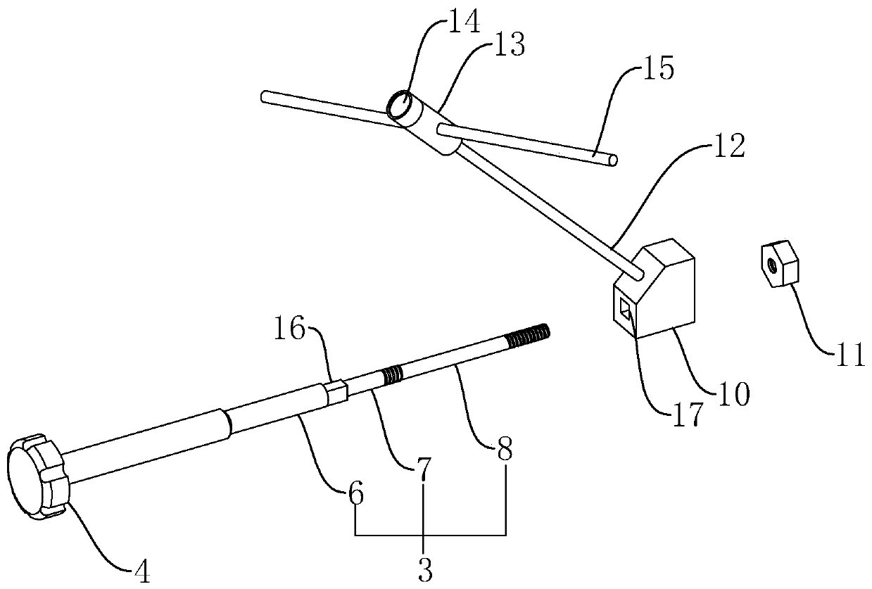
[0041] like image 3 As shown, an acetabular outer cup installation locator differs from Embodiment 1 in that a square positioning column 16 is formed on the side of the connecting section 6 facing the installation section 7, and a square positioning column 16 is formed on the mounting sleeve 10 to fit the positioning column 16. Matching positioning groove 17.

Embodiment 3

[0043] like Figure 4 As shown, an acetabular cup installation positioner is different from Embodiment 1 in that the operating rod assembly 1 includes a central rod 3 and a sleeve 18 sheathed on the outside of the central rod 3 .

[0044] like Figure 4 As shown, the casing 18 includes an inner tube 19 and an outer tube 20, and the left end of the inner tube 19 is threaded or fixed with a positioning block 21 in other detachable connection ways. A square with rounded corners, and the size of the positioning block 21 gradually decreases from right to left. like Figure 5 and Image 6 As shown, the right end surface of the positioning block 21 is formed with a first circular groove 22 . The position on the outer wall of the inner tube 19 close to the right end is fixed or the limiting ring 23 is integrally formed, and the installation sleeve 10 is sleeved on the position where the inner tube 19 abuts against the right side of the limiting ring 23 . A mounting groove 24 is f...


PUM


Abstract

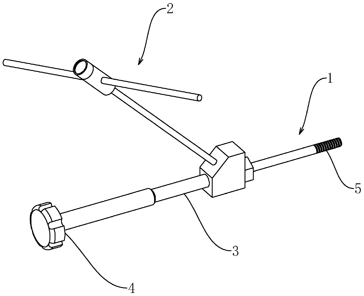
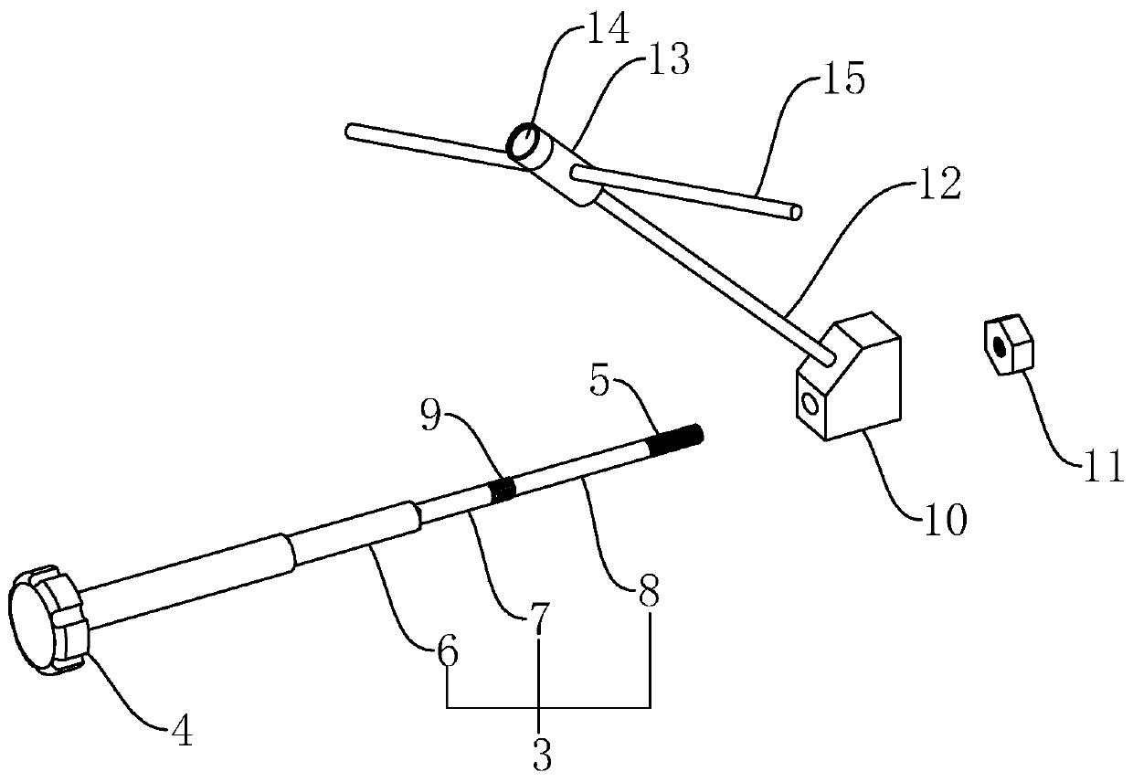
The invention relates to an acetabulum outer cup mounting positioner. The acetabulum outer cup mounting positioner has the advantage of being capable of assisting in positioning the implantation angleof an acetabulum outer cup. The invention discloses an acetabulum outer cup mounting positioner that includes an operating rod assembly and further comprises an angle indicating assembly located on the operating rod assembly; the operating rod assembly comprises a center rod, the angle indicating assembly comprises an inclined rod, a 45-degree included angle is formed between the inclined rod andthe center rod, and a gradienter indicating that the horizontal plane is perpendicular to the axis of the inclined rod is installed at the upper end of the inclined rod. An acetabulum outer cup of ahuman body has an inclination degree and a forward inclination degree in the acetabulum, the inclination degree and the waist width direction form an included angle of about 15 degrees, and the forward inclination degree is about 45 degrees. The inclined rod is arranged to form the 45-degree included angle with the central rod, so that when a person lies flat and the gradienter indicates the horizontal plane, the inclined rod is vertically upward, and the central rod is just at the 45-degree inclination angle at the moment. A doctor does not need to judge whether the forward inclined degree ofthe implanted acetabulum outer cup exceeds the safety angle range or not according to experience.

Description

technical field [0001] The invention relates to the technical field of medical instruments, in particular to an acetabular outer cup mounting positioner. Background technique [0002] Hip reconstruction is a successful solution for demanding patients with degenerative hip disease, and for younger patients with hip dysplasia or traumatic arthritis, hip replacement can improve mobility and relieve pain. [0003] Existing authorized announcement number is that the utility model patent of CN203539495U discloses a kind of acetabular cup installation positioning device. In this scheme, after the shaft is connected to the acetabular cup, the acetabular cup is implanted from the surgical incision, which is beneficial to reduce the wound size of the surgical instrument introduction port. [0004] The above-mentioned existing technical solutions have the following defects: after inserting the surgical instrument in the case of a small wound, the doctor's field of vision is limited, a...

Claims


Application Information

Patent Timeline
Patent Type & Authority Applications(China)
IPC IPC(8): A61F2/46
CPCA61F2/4609A61F2002/4687
Inventor 解凤宝史春宝陈立叶
Owner BEIJING CHUNLIZHENGDA MEDICAL INSTR
Learn More