Plate-type flame arrester with wavy micro-channels

A wave-shaped, micro-channel technology, applied in fire rescue and other directions, can solve the problems of prolonged cleaning cycle, easy deposition of ash, large fluid resistance, etc., and achieve the effect of prolonged cleaning cycle, good fire resistance and low fluid resistance

Inactive Publication Date: 2020-06-16
CHANGZHOU INST OF TECH
View PDF6 Cites 0 Cited by
  • Summary
  • Abstract
  • Description
  • Claims
  • Application Information

AI Technical Summary

Problems solved by technology

[0003] The invention solves the problem that the corrugated plate flame arrester with a triangular microchannel is mostly used in the related art, and its fluid resistance is large, it is easy to deposit ashes, and it needs to be cleaned in a short time, and a microchannel with a wave shape is proposed. The plate flame arrester has no sharp or right angles in the channel, and the fluid resistance is small when the gas passes through; because the micro channel is wavy and smooth, it is not easy to deposit ashes after gas combustion, and the cleaning cycle can be extended

Method used


Image

  • Plate-type flame arrester with wavy micro-channels
  • Plate-type flame arrester with wavy micro-channels

Examples


Embodiment 1

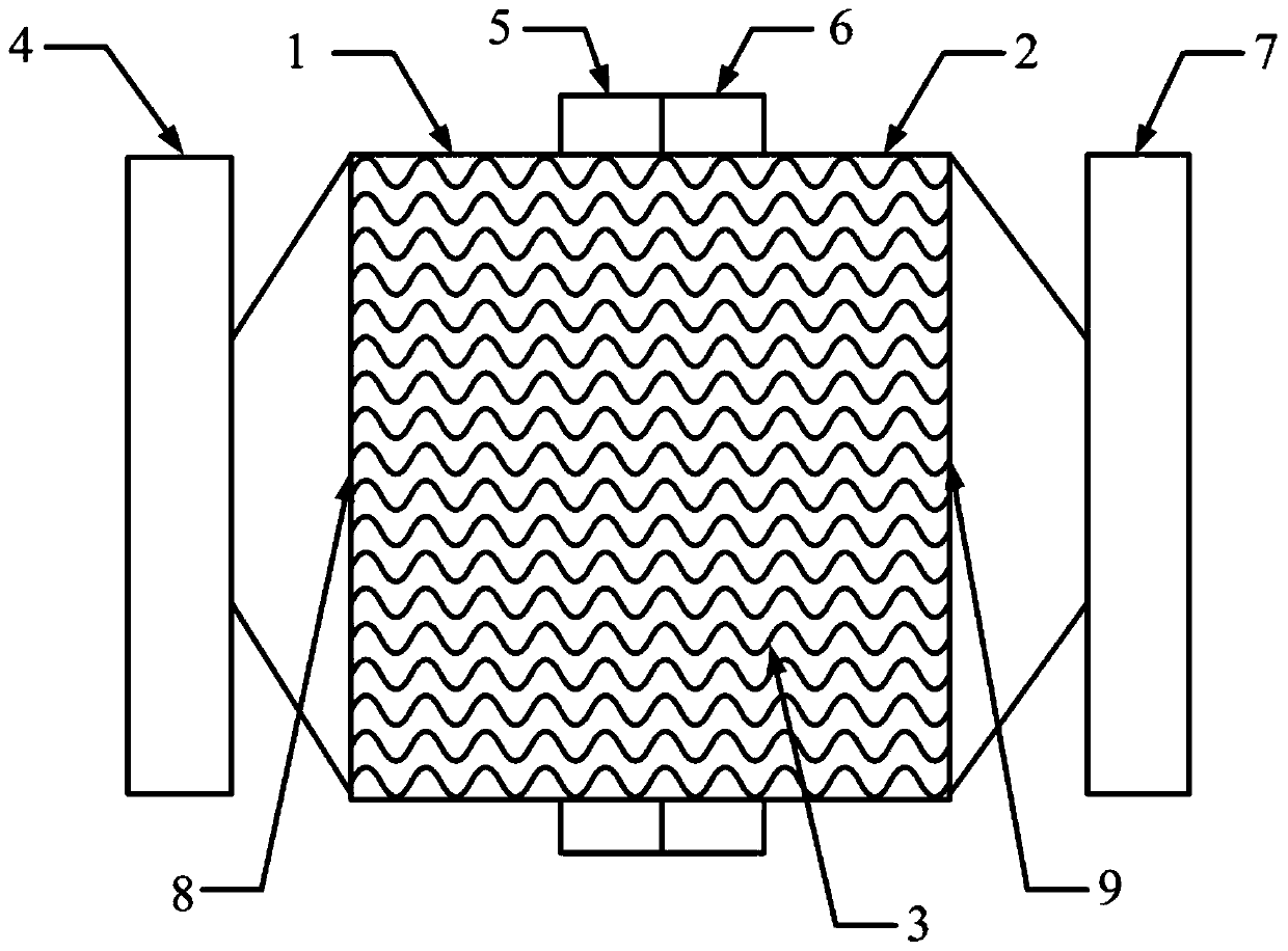
[0017] Such as Figures 1 to 2 As shown, a plate flame arrester with corrugated microchannels includes a cylinder and a fire arresting core 3. The cylinder includes a first cylinder 1 and a second cylinder 2, and the first cylinder 1 is connected by a flange II5 It is connected with flange III6, specifically, flange II5 and flange III6 are sealed and connected by bolts and nuts, and gaskets are also provided between the bolts and nuts; the other end of the first cylinder 1 is also provided with flange I4 , the other end of the second cylinder 5 is also provided with a flange IV7 for connection with the pipeline; the fire retardant core 3 is arranged in the cylinder, and the two ends of the fire retardant core 3 are respectively provided with a first support plate 8 and a second support Plate 9, the first cylinder expansion cavity is formed between flange I4 and the first support plate 8, and the second cylinder expansion cavity is formed between flange IV7 and the second suppo...

Embodiment 2

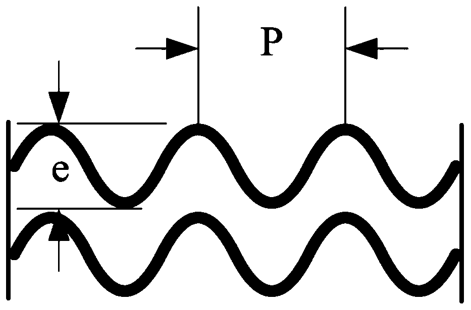
[0023] The difference from Example 1 is that in this example, the wave height e of the stainless steel plate is 1 mm, the wavelength P is 100 mm, the distance between the microchannels formed by the stainless steel plate is 20 mm, and the expansion cavity of the first cylinder and the expansion cavity of the second cylinder are The expansion angles are all 10°.

Embodiment 3

[0025] Different from Embodiment 1, in this embodiment, the wave height e of the stainless steel plate is 10mm, the wavelength P is 100mm, the distance between the microchannels formed by the stainless steel plate is 0.5mm, and the expansion chamber of the first cylinder and the expansion chamber of the second cylinder The expansion angle of the cavity is 60°.


PUM


Abstract

The invention relates to the technical field of flame arresters, in particular to a plate-type flame arrester with wavy micro-channels. The plate-type flame arrester comprises cylinder bodies and a fire arresting core, wherein the cylinder bodies comprise a first cylinder body and a second cylinder body; the first cylinder body and the second cylinder body are connected by a flange II and a flangeIII; the other end of the first cylinder body is also provided with a flange I; the other end of the second cylinder body is also provided with a flange IV; the fire arresting core is arranged in thecylinder bodies; two ends of the fire arresting core are separately provided with a first supporting plate and a second supporting plate; a first cylinder expansion cavity is formed between the flange I and the first supporting plate; a second cylinder expansion cavity is formed between the flange IV and the second supporting plate; the fire arresting core is formed by combining a plurality of stainless steel plates of wavy structures with the same waveform; a micro-channel is formed between every two stainless steel plates; wave crests of every two adjacent stainless steel plates are aligned; and wave troughs of every two adjacent stainless steel plates are aligned. The plate-type flame arrester with the wavy micro-channels is low in fluid resistance, and ashes are not prone to be deposited.

Description

technical field [0001] The invention relates to the technical field of flame arresters, in particular to a plate flame arrester with corrugated microchannels. Background technique [0002] Flame arresters are usually installed in flammable and explosive gas pipelines or at the inlet and outlet of equipment. It is a safety device that prevents the passage of flames and allows gas to pass through. Existing flame arresters mostly use corrugated plate flame arresters with triangular microchannels, which have a good flame arresting effect, but there are acute or right angles in the channels, resulting in large fluid resistance; in addition, corrugated plate microchannels with a triangular structure are easy to deposit ashes after gas combustion , Therefore, it needs to be cleaned in a short time. Therefore, it is urgent to develop a micro-channel flame arrester with small fluid resistance and not easy to deposit ash. Contents of the invention [0003] The invention solves the ...

Claims


Application Information

Patent Timeline
IPC IPC(8): A62C4/04
CPCA62C4/04
Inventor 李若嵩康梓洲石思溢蒋夫花曹桂萍刘宝亮丁琳琳
Owner CHANGZHOU INST OF TECH
Why Eureka
Try Eureka