Casting waste sand regeneration device

A regeneration device and casting waste sand technology, which is applied in the direction of casting molding equipment, manufacturing tools, cleaning/processing machinery of casting mold materials, etc., can solve the problems of reduced regeneration efficiency, complex overall structure, high cost, etc., to reduce vibration, damage reduction effect

Inactive Publication Date: 2020-06-16
姚仿英
View PDF1 Cites 2 Cited by
  • Summary
  • Abstract
  • Description
  • Claims
  • Application Information

AI Technical Summary

Problems solved by technology

[0002] After the sand casting is completed, a certain amount of waste sand will be produced. The waste sand regeneration device in the prior art still has some shortcomings when processing the waste sand. For example, the waste sand regeneration device in the prior art mostly includes a grinding mechanism, a sieve Sub-organization, waste collection mechanism and reclaimed sand collection mechanism, the overall structure of the equipment is relatively complex, the cost is also high, and the operation is relatively inconvenient, which will also lead to a reduction in regeneration efficiency

Method used


Image

  • Casting waste sand regeneration device
  • Casting waste sand regeneration device
  • Casting waste sand regeneration device

Examples


Embodiment 1

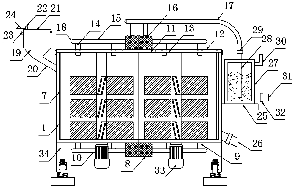
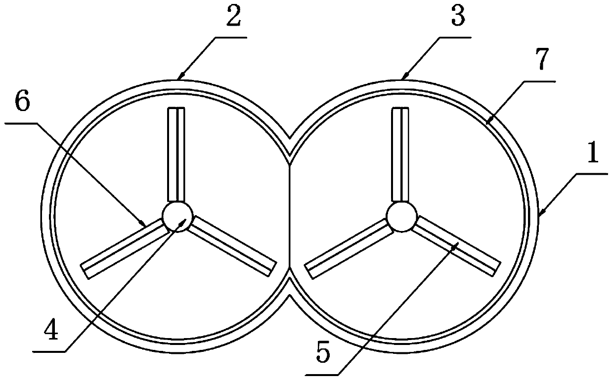
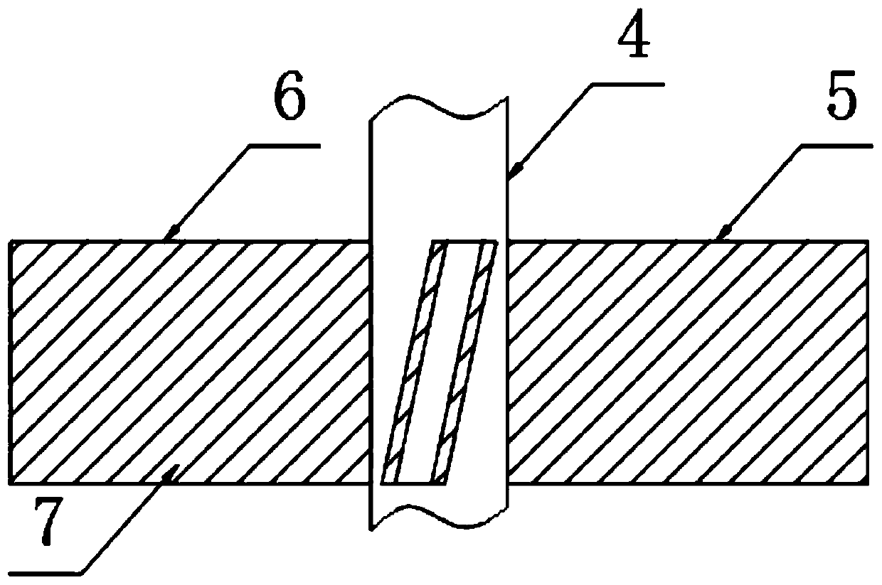
[0026] The present invention provides such Figure 1-4 The casting waste sand regeneration device shown includes a casing 1, and the casing 1 includes a left casing 2 and a right casing 3, and the right casing 3 is arranged on the side of the left casing 2, and the left casing 2 Both the casing 2 and the bottom of the inner cavity of the right casing 3 are provided with a rotating rod 4, and a stirring mechanism 5 is fixed on the outside of the rotating rod 4, and the stirring mechanism 5 includes a plurality of stirring blades 6. The casing 1 The inner wall and the side of the stirring fan blade 6 are fixed with a frosted layer 7, the bottom of the casing 1 is fixed with a high-pressure hot air blower 8 and an air intake branch pipe 9 is installed through it, and the end of the air intake branch pipe 9 is provided with an air intake main pipe 10. The top of the casing 1 is provided with a top plate 11, and both sides of the top plate 11 are provided with a top cover 12. The b...

Embodiment 2

[0029] Further, in the first embodiment above, the end of the intake main pipe 10 is connected to the high-pressure hot air blower 8 , and the air intake branch pipe 9 is connected to the high-pressure hot air blower 8 through the main intake pipe 10 .

[0030] Further, in the above-mentioned embodiment 1, the ends of the inlet main pipe 10, the outlet main pipe 15 and the exhaust pipe 17 are all fixedly provided with rubber sealing plugs 18, so that the ends of the inlet main pipe 10 and the outlet main pipe 15 and the end of the exhaust pipe 17 are sealed.

[0031] Further, in the above-mentioned embodiment 1, a hopper 19 is provided on one side of the casing 1, and the bottom of the hopper 19 is fixed with a feeding pipe 20, and the feeding pipe 20 runs through the side wall of the casing 1 and extends to Inside the casing 1 , the top of the hopper 19 is provided with a sealing cover 21 , the top of the sealing cover 21 is fixed with a connecting block 22 and the side is fi...


PUM


Abstract

The invention discloses a casting waste sand regeneration device which comprises a machine enclosure. The machine enclosure comprises a left machine enclosure body and a right machine enclosure body.The right machine enclosure body is arranged on one side of the left machine enclosure body. Rotating rods penetrate through the bottoms of inner cavities of the left machine enclosure body and the right machine enclosure body. A stirring mechanism is fixedly arranged on the outer side of each rotating rod. Each stirring mechanism comprises multiple stirring fan blades. Frosting layers are fixedlyarranged on the inner wall of the machine enclosure and the side faces of the stirring fan blades. A high-pressure air heater is fixedly arranged at the bottom of the machine enclosure, and air inletbranch pipes are arranged on the machine enclosure in a penetrating manner. An air inlet main pipe is arranged at the ends of the air inlet branch pipes. A top plate is arranged at the top of the machine enclosure. Top covers are arranged on the two sides of the top plate. A sealing ring is arranged at the bottom of each top cover in a nested manner. Air outlet branch pipes are arranged on each top cover in a penetrating manner. By means of the casting waste sand regeneration device, the structure of equipment in the prior art is simplified effectively, casting waste sand regeneration is carried out effectively, meanwhile, the equipment structure is quite simple, the equipment cost is low, operation is quite convenient, the regeneration efficiency is effectively improved, and design is reasonable.

Description

technical field [0001] The invention relates to the field of foundry technology, in particular to a device for regenerating foundry waste sand. Background technique [0002] After the sand casting is completed, a certain amount of waste sand will be produced. The waste sand regeneration device in the prior art still has some shortcomings when processing the waste sand. For example, the waste sand regeneration device in the prior art mostly includes a grinding mechanism, a sieve Sub-organization, waste collection mechanism and reclaimed sand collection mechanism, the overall structure of the equipment is relatively complex, the cost is also high, and the operation is relatively inconvenient, which will also lead to a reduction in regeneration efficiency. [0003] Therefore, it is necessary to invent a casting waste sand regeneration device to solve the above problems. Contents of the invention [0004] The object of the present invention is to provide a casting waste sand ...

Claims


Application Information

Patent Timeline
Patent Type & Authority Applications(China)
IPC IPC(8): B22C5/04B22C5/08
CPCB22C5/0431B22C5/08
Inventor 姚仿英
Owner 姚仿英
Why Eureka
Try Eureka