[0025] The technical solutions in the embodiments of the present invention will be clearly and completely described below in conjunction with the accompanying drawings in the embodiments of the present invention. Obviously, the described embodiments are only a part of the embodiments of the present invention, rather than all the embodiments. Based on the embodiments of the present invention, all other embodiments obtained by those of ordinary skill in the art without creative work shall fall within the protection scope of the present invention.
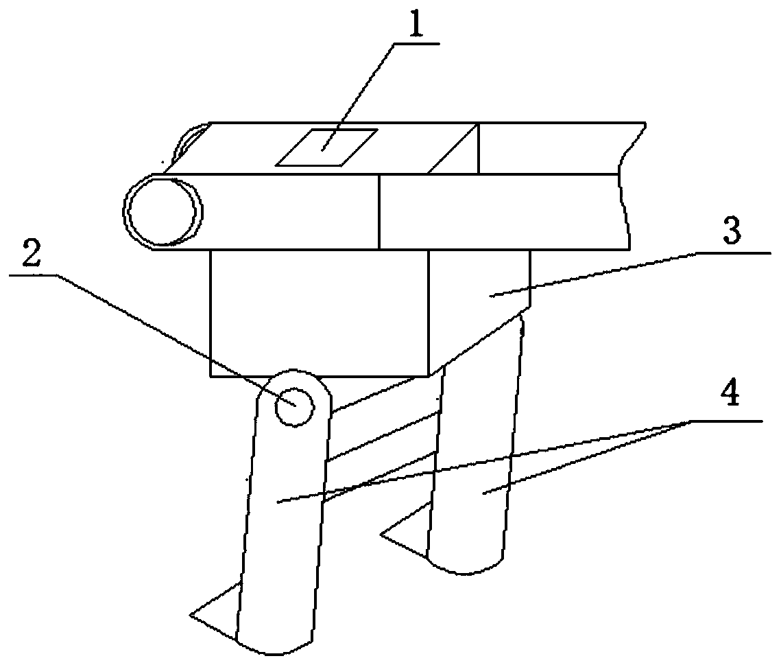
[0026] see figure 1 , An electronic parking control module for the automatic parking system of an electric moped, including a control circuit board 1 and a load sensor 2. The control circuit board 1 is provided with a single-chip minimum system U4 (see Figure 4 ), vehicle speed detection circuit, load detection circuit and logic control circuit, the single-chip minimum system U4 drives the parking motor 3 through the logic control circuit so that the parking support frame 4 connected to the parking motor 3 is supported or recovered, and the load sensor 2 is set The parking motor 3 and the parking support frame 4 are connected to a pin-type load sensor on the pin.
[0027] see figure 2 When the electric door lock is turned off and the driver of the electric assisted vehicle presses the start switch, the electronic parking control module drives the parking motor 3 to run forward, so that the parking support frame 4 starts to prop up, and then the load sensor 2 detects the support Actual load. When the load is normal, the parking support frame 4 is supported in place to realize automatic parking; when the parking support frame 4 is being propped up, the load sensor 2 detects overload, and the parking support frame 4 is retracted until After the overload is lifted, the vehicle can be parked normally. At the same time, when the electric power-assisted vehicle needs to be started, the electric door lock is turned on, and the start switch is pressed again, and the electronic parking control module realizes the reverse driving of the parking motor 3, so that the parking support frame 4 is retracted.
[0028] see image 3 , The control circuit board 1 is provided with a system power supply circuit, the system power supply circuit includes a PFM type step-down DC-DC voltage converter U2, an input end of a transformer T1 connected to the PFM type step-down DC-DC voltage converter U2, and an input end The three-terminal voltage regulator chip U1 is connected to the output terminal of the transformer T1, the input terminal of the PFM type step-down DC-DC voltage converter U2 is connected to the output voltage V+ of the vehicle battery, and the output terminal of the transformer T1 outputs 12V power supply, three-terminal voltage regulation The output terminal of the chip U1 outputs a 5V power supply VCC, and the 5V power supply VCC is connected to the VCC pin of the smallest system U4 of the single-chip microcomputer. The on-board battery voltage v+ of the two-wheeled electric moped has a large range, which generally varies in the range of tens of volts DC, and needs to be adjusted to the power supply required by the system. U2 is a primary-side control, constant current and constant voltage optional PFM type step-down DC-DC voltage converter for flyback switching power supply. It integrates a power switch and can ignore the feedback circuit of linear optocoupler. It can achieve low static power consumption, low noise and other performance, and high conversion efficiency. First, the PFM type step-down DC-DC voltage converter U2 excites the transformer T1 and obtains a 12V DC power supply through rectification, and then obtains a relatively stable 5V power supply VCC through the three-terminal voltage regulator chip U1.
[0029] see Figure 4 , The smallest single-chip microcomputer system U4 integrates multiple 12-bit successive approximation ADCs, which can be used as analog-to-digital conversion of load detection signal (ZaiHe_Det), vehicle battery voltage detection signal (BAR_V_Det), speed detection signal (ZhuanS_Det), etc. It integrates a high-stability RC high-frequency oscillator circuit, power-on reset circuit, etc., and can realize in-system programming (ISP) through its serial port controller. P6 in the figure is its ISP interface.
[0030] The logic control circuit includes an electric door lock signal input circuit, an anti-theft signal input circuit, a power-on start circuit, a motor forward and reverse relay control circuit, and a parking motor working state acquisition circuit.
[0031] see Figure 4 with Figure 5 , The speed detection circuit includes diode D7, resistor R29, transient suppression diode Z11, capacitor C16 and resistor R32, motor speed and anti-theft signal connector P4 (see Figure 7 ) The Speed pin used for the phase line signal output of the electric motor of the electric assisted vehicle is connected to the speed collection end of the vehicle speed detection circuit, that is, the anode of the diode D7. One end of the resistor R29 and the cathode of the transient suppression diode Z11 are connected to the cathode of the diode D7. The other end of resistor R29, one end of capacitor C16 and one end of resistor R32 are connected to each other as the output end of the speed detection circuit and connected to the load collection pin (pin 20) of the smallest system U4 of the single-chip microcomputer. The anode of transient suppression diode Z11 and the capacitor The other end of C16 and the other end of resistor R32 are both grounded. In order to prevent misoperation during the parking process of the electric assisted vehicle, the actual driving speed of the electric assisted vehicle needs to be detected. The specific method is to take the signal (Speed) from the phase line of the electric assisted vehicle driving motor. PWM signal, after the first-order RC low-pass filter is performed on the signal, the DC signal (ZhuanS_Det) is obtained by appropriately dividing the voltage and sent to the ADC2 (pin 20) of the microcontroller minimum system U4 for analog-to-digital conversion to realize the speed detection of the electric moped .
[0032] see Figure 4 with Image 6 The load detection circuit includes load sensor connector P7, operational amplifier U5A, resistor R30, resistor R33, resistor R28, resistor R34, capacitor C15, capacitor C18, resistor R31, and capacitor C17. One end of resistor R30 is plugged into the load sensor The differential signal SIG-port of the device P7 is connected, the other end of the resistor R30 is connected to the inverting input end of the operational amplifier U5A, and the other end of the resistor R30 is grounded through the capacitor C15, and the difference between one end of the resistor R33 and the load sensor connector P7 The signal SIG+ port is connected, the other end of the resistor R33 is connected to the non-inverting input end of the operational amplifier U5A, the other end of the resistor R33 is grounded through the capacitor C18, the resistor R28 is connected between the inverting input end and the output end of the operational amplifier U5A, and the resistor R34 One end of the resistor is connected to the non-inverting input of the operational amplifier U5A, the other end of the resistor R34 is grounded, one end of the resistor R31 is connected to the output of the operational amplifier U5A, and the other end of the resistor R31 and one end of the capacitor C17 are connected to each other as the output of the load detection circuit The terminal is connected to the load collection pin (pin 2) of the smallest system U4 of the single-chip microcomputer, and the other terminal of the capacitor C17 is grounded. The output of the load sensor connector P7 is a millivolt differential voltage signal, which needs to be amplified before it can be converted by the ADC inside the microcontroller's smallest system U4, by rail-to-rail operational amplifier U5A, resistor R30 The differential proportional amplifier circuit composed of resistor R33, resistor R28, resistor R34, etc. realizes the amplification of the output signal of the load sensor 2, and then connects to the ADC0 channel of the smallest system U4 of the single-chip microcomputer to realize the process of supporting the parking support frame 4. Load detection in.
[0033] see Figure 4 with Figure 7 , The electric door lock signal input circuit includes resistor R6, resistor R8, capacitor C8, transient suppression diode Z3, one end of the resistor R6 is used as the input end of the electric door lock signal input circuit and the electric door lock and start switch connector P3 DianMS pin is connected, the other end of resistor R6, one end of resistor R8, one end of capacitor C8, and the cathode of transient suppression diode Z3 are connected to each other as the output terminal of the electric door lock signal input circuit and the electric door lock signal of the smallest microcontroller system U4 The acquisition pin DMS (pin 4) is connected; the anti-theft signal input circuit includes diode D4, resistor R7, transient suppression diode Z4 and capacitor C9. The anode of diode D4 is used as the input terminal of the anti-theft signal input circuit and the anti-theft signal and speed acquisition The FangDao pin of connector P4 is connected, one end of resistor R7 is connected to the cathode of diode D4, the other end of resistor R7, the cathode of transient suppression diode Z4 and one end of capacitor C9 are connected to each other as the output end of the anti-theft signal input circuit and The anti-theft signal acquisition pin FD (pin 5) of the smallest system U4 of the single-chip microcomputer is connected, the anode of the transient suppression diode Z4 and the other end of the capacitor C9 are both grounded; the power-on startup circuit includes diode D6, resistor R16 and resistor R17, diode The negative pole of D6 is used as the input terminal of the power-on start circuit to connect with the QiDong pin of the electric door lock and start switch connector P3. One end of the resistor R16 and one end of the resistor R17 are connected to each other to start the motor forward and reverse relay control circuit. The control end is connected, the anode of diode D6 is connected to the other end of resistor R16, and the other end of resistor R17 is connected to the vehicle battery; the motor forward and reverse relay control circuit includes a dedicated MOS tube drive chip U3, N-channel MOS tube Q1, and PNP type Transistor Q2, motor reverse relay J1 and motor forward relay J2, the base of PNP type transistor Q2 is used as the start control end of the motor forward and reverse relay control circuit, the normally open contact of motor reverse relay J1 and the motor forward relay The normally open contacts of J2 are connected to the collector of the PNP transistor Q2, that is, the power output terminal of the forward and reverse relay control circuit. The emitter of the PNP transistor Q2 serves as the power input terminal of the motor forward and reverse relay control circuit and the vehicle battery The positive connection of the motor reverse relay J1 and the normally closed contact of the motor forward relay J2 are connected to the collector of the N-channel MOS transistor Q1, and the control terminal of the motor reverse relay J1 is connected to the parking motor The reverse control terminal Motor- of the forward and reverse control signal connector P1 is connected, and the control terminal of the motor reverse relay J2 is connected to the forward and reverse control terminal Motor+ of the parking motor forward and reverse control signal connector P1, N channel The source of the MOS tube Q1 is connected to the motor control pin DR2 (pin 14) of the smallest system U4 of the single-chip microcomputer through the dedicated drive chip U3 for the MOS tube, and the gate of the MOS tube Q1 is grounded through a resistor R10; the parking motor working state acquisition circuit includes There are resistor R9, resistor R12, capacitor C10 and transient suppression diode Z5, resistor R9 One end of the resistor R12 and one end of the resistor R12 are connected to the gate of the MOS transistor Q1. The other end of the resistor R12, one end of the capacitor C10, and the cathode of the transient suppression diode Z5 are connected to each other and then connected to the motor state acquisition pin Motor_Det of the smallest single-chip microcomputer system U4 (Pin 19) is connected, the other end of the resistor R9, the other end of the capacitor C10 and the positive electrode of the transient suppression diode Z5 are all grounded; the vehicle battery (BAT+, GND are the positive and negative electrodes of the vehicle battery) is supplied to the electronics after the resettable fuse F1 The parking control module is powered, and the real-time voltage of the power supply is collected through the pin BAT_V_Det (pin 1) of the smallest system U4 of the single-chip microcomputer.
[0034] Figure 7 The P1-P5 are all standard connectors, which are used to connect the relevant signal wires to the control circuit board 1. Among them, Motor+ is the forward rotation control signal of the parking motor, Motor- is the reverse control signal of the parking motor, XW_DW is the lower limit signal of the parking support frame, XW_UP is the upper limit signal of the parking support frame, and QiDong is the start Switch signal, DianMS is the electric door lock signal, FangDao is the anti-theft signal on the original electric moped, Speed is the phase wire speed signal of the electric moped driving motor, BAT+ and GND are the positive and negative poles of the car battery.
[0035] Whether the electric door lock is open is judged by the minimum system U4 of the single-chip microcomputer through the logic level of the DMS signal. When the signal input from pin 4 of the minimum system U4 of the single-chip microcomputer is low, it means that the electric door lock is not opened, otherwise it is opened. The original anti-theft signal FangDao of the electric moped is sent to pin 5 of the minimum system U4 of the single-chip microcomputer through diode D4 and resistor R7. The minimum system U4 of single-chip microcomputer determines whether the parking support frame 4 is retracted according to the anti-theft signal. When the start switch is pressed, the start switch signal QiDong is connected to the system power ground, and the tertiary tube Q2 is turned on, so that the power V_JDQ output by the tertiary tube Q2 is connected to the normally open contact of the motor reverse relay J1 and the motor forwards. The normally open contact of relay J2 is connected to provide power supply conditions for the rotation of the parking motor 3. Under the premise that the electric door lock and the start button are pressed, the single-chip minimum system U4 sends a parking motor control signal to the MOS tube dedicated drive chip U3, the MOS tube dedicated driver chip U3 drives the N-channel MOS tube Q1 to turn on, thereby driving the parking support frame 4 to prop up; and when the electric door lock is closed and the start switch is pressed, the above circuit makes the parking motor 3 reverse, and the parking support frame 4 retracts. After the parking support frame 4 is retracted and supported, the connector P2 inputs the XW_DW or XW_UP signal. At this time, the coils of the motor reverse relay J1 and the motor forward relay J2 lose power, thereby cutting off the power supply of the parking motor 3 , The retracting or supporting action of the parking support frame 4 stops. The minimum system U4 of the single-chip microcomputer can determine the working status of the parking motor 3 by acquiring the Motor_Det signal. When the input level of pin 19 of the minimum system U4 of the single-chip microcomputer is low, the parking motor 3 is not working and the input level is high. , The parking motor 3 is working.
[0036] Although the embodiments of the present invention have been shown and described, those of ordinary skill in the art can understand that various changes, modifications, and substitutions can be made to these embodiments without departing from the principle and spirit of the present invention. And variations, the scope of the present invention is defined by the appended claims and their equivalents.