Pushers and Brakes

A pusher and brake arm technology, applied in the field of braking equipment, can solve the problems of high energy consumption of the pusher, high error rate, heating of the pusher components, etc., and achieve high transmission stability and transmission precision, high transmission power, Effect of constant gear ratio

Active Publication Date: 2022-03-15
HUNAN UNIV
View PDF6 Cites 0 Cited by
  • Summary
  • Abstract
  • Description
  • Claims
  • Application Information

AI Technical Summary

Problems solved by technology

Therefore, the hydraulic pump needs to work continuously so that the existing pusher consumes a lot of energy and has high requirements for the stability of the hydraulic system; in addition, the hydraulic pump runs for a long time, and its heat will cause the various parts of the pusher to heat up, which is easy to The aging of the seal due to heat will reduce the service life, and in severe cases, oil leakage will occur, increasing the workload of maintenance and repair; moreover, the pusher of the prior art has many types and quantities of parts, the operation is more complicated, and the error rate is relatively high

Method used


Image

  • Pushers and Brakes
  • Pushers and Brakes
  • Pushers and Brakes

Examples


Embodiment Construction

[0032] Specific embodiments of the present invention will be described in detail below in conjunction with the accompanying drawings. It should be understood that the specific embodiments described here are only used to illustrate and explain the present invention, and are not intended to limit the present invention.

[0033] In the description of the present invention, it should be noted that unless otherwise specified and limited, the terms "connection" and "arrangement" should be understood in a broad sense, for example, it can be a fixed connection or a detachable connection, or a Integral connection; it can be a direct connection, or an indirect connection through an intermediary, and it can be the internal communication of two elements or the interaction relationship between two elements. Those of ordinary skill in the art can understand the specific meanings of the above terms in the present invention according to specific situations.

[0034] It should be understood t...


PUM


Abstract

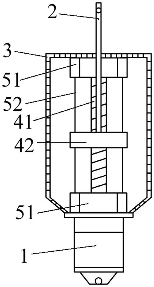
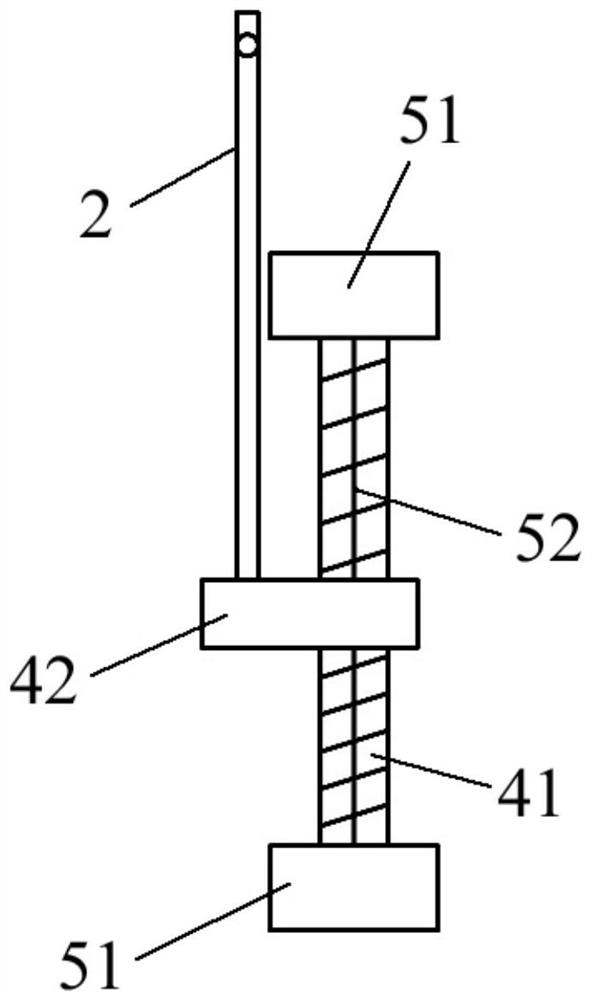
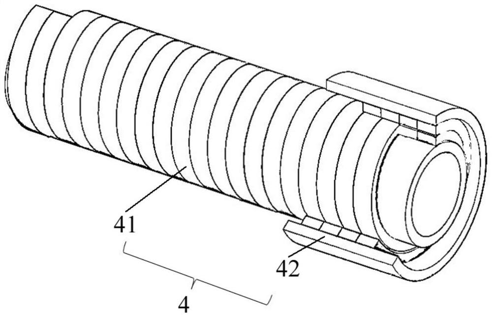
The invention relates to braking equipment, and specifically discloses a pusher, which includes a guide device, a drive device, a magnetic screw and a push rod, and the magnetic screw and the guide are accommodated in a housing; the magnetic screw includes A magnetic screw and a magnetic nut, the magnetic nut is coaxially sleeved on the magnetic screw with an air gap between them; the driving device is fixedly connected to the magnetic screw, and the push rod One end is fixedly connected with the magnetic nut, and the other end protrudes from the housing; the driving device is suitable for driving the magnetic screw to rotate, so as to drive the magnetic nut to move back and forth along the magnetic screw through the magnetic coupling force, And limit its moving trajectory by the guide device. Furthermore, the invention also relates to a brake. The pusher of the invention has a simple structure, and utilizes magnetic force transmission to realize isolated transmission.

Description

technical field [0001] The present invention relates to braking equipment, in particular to a pusher. Furthermore, a brake is also involved. Background technique [0002] The pusher is often matched with the brake, which is used for deceleration, parking brake and safety protection of mechanical equipment in lifting, belt transportation, port loading and unloading, metallurgy, mining, construction and other industries. The hydraulic pusher in the prior art mainly includes a fuel tank, a hydraulic pump and a hydraulic cylinder, wherein, when the hydraulic pusher is powered on, the oil stored in the fuel tank is sent into the hydraulic cylinder under the action of the hydraulic pump, and as the hydraulic cylinder The pressure of the oil inside gradually increases, and the oil pushes the piston, so that the push rod on the piston extends upwards under the drive of the piston. After the hydraulic pusher is powered on, the oil flows back into the oil tank, and the piston drives ...

Claims


Application Information

Patent Timeline
Patent Type & Authority Patents(China)
IPC IPC(8): H02K49/10H02K7/06F16D65/28F16D121/18
CPCH02K49/106H02K7/06F16D65/28F16D2121/18
Inventor 刘晓肖罗鹏崔鹤松黄守道
Owner HUNAN UNIV
Why Eureka
Try Eureka