Borehole fluid lifting device and method

A lifting device and internal fluid technology, which is applied to the valve device of wellbore/well, production fluid, earth-moving drilling, etc., can solve problems such as hindering the normal production of oil wells, reducing the working efficiency of pumps, and pulling over the pumping unit, etc. Achieve the effect of avoiding corrosion and wear of mechanical structure, avoiding eccentric wear of pipe and rod, and doubling production efficiency

Pending Publication Date: 2020-06-16
CHINA PETROLEUM & CHEM CORP +1
View PDF6 Cites 0 Cited by
  • Summary
  • Abstract
  • Description
  • Claims
  • Application Information

AI Technical Summary

Problems solved by technology

[0002] Sand production in oil wells has always been one of the important problems that hinder the normal production of oil wells. For ordinary plunger pumps, it is easy to cause production problems and safety accidents such as sand stuck in the oil well pump, plunger wear, and pumping unit being pulled over due to sand stuck in the pump. ; For screw pumps, it is easy to lie in the well due to sand sticking; for electric submersible pumps, it will cause unit parts to wear or even sand sticking, which will affect the working life of the unit
In addition, formation fluids are mostly highly corrosive, and the key working parts of various pumps are in direct contact with formation fluids, causing corrosion and reducing the working efficiency of the pumps
At present, the commonly used methods are to adopt various anti-sand and anti-corrosion methods such as coating of the pump body, opening sand control tanks, and adding corrosion inhibitors, which have achieved certain effects, but the moving parts of the pump are still subject to wear and corrosion due to direct contact with the formation liquid.

Method used


Image

  • Borehole fluid lifting device and method

Examples


Embodiment Construction

[0024] The following will clearly and completely describe the technical solutions in the embodiments of the present invention with reference to the accompanying drawings in the embodiments of the present invention. Obviously, the described embodiments are only some, not all, embodiments of the present invention. Based on the embodiments of the present invention, all other embodiments obtained by persons of ordinary skill in the art without making creative efforts belong to the protection scope of the present invention.

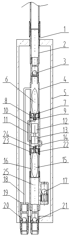
[0025] see figure 1 , the present invention provides a technical solution: a fluid lifting device in a well, including an outer pipe 5, a two-way drive lifting mechanism, an upper nipple 1, an upper pipe string liquid inlet valve 20, a lower pipe string liquid inlet valve 21, an upper Drain valve 3, lower drain valve 17, the upper nipple is installed in the upper nipple installation hole opened at the upper end of the outer pipe, and the upper pipe string inle...


PUM


Abstract

The invention discloses a borehole fluid lifting device and method. Two tubular column inlet channels are arranged for stratum output liquid, one channel is that when a lower bag shrinks, borehole fluid enters a production tubular column through a lower tubular column liquid inlet valve; when the lower bag is increased, the borehole fluid enters an airtight annular space formed by closely connecting an upper short section, an upper tubular column liquid inlet valve and the lower tubular column liquid inlet valve through a lower liquid discharging valve, and then the borehole fluid enters the tubular column through a tubular column liquid inlet. The other channel is that when an upper bag shrinks, the borehole fluid enters the upper tubular column liquid inlet valve, and then enters an upper bag short section along an upper tubular liquid inlet channel; and when the upper bag is increased, output liquid is squeezed to the upper tubular column by an upper liquid discharging valve. The borehole fluid is only in touch with the outer surface of a bag, the exterior of a motor, the exterior of a gear pump and the like during application, cannot enter important movement parts such as the gear pump, and thus the influence of oil well corrosion and sand production on liquid yield equipment is thoroughly avoided.

Description

technical field [0001] The invention relates to the technical field of oil production in the petroleum industry, in particular to an in-well fluid lifting device and method. Background technique [0002] Sand production in oil wells has always been one of the important problems that hinder the normal production of oil wells. For ordinary plunger pumps, it is easy to cause production problems and safety accidents such as sand stuck in the oil well pump, plunger wear, and pumping unit being pulled over due to sand stuck in the pump. ; For the screw pump, it is easy to lie in the well due to sand stuck; for the electric submersible pump, it will cause the unit components to wear or even sand stuck, which will affect the working life of the unit. In addition, the formation fluid is mostly highly corrosive, and the key working parts of various pumps are in direct contact with the formation fluid, causing corrosion and reducing the working efficiency of the pump. At present, the ...

Claims


Application Information

Patent Timeline
Patent Type & Authority Applications(China)
IPC IPC(8): E21B43/12E21B34/08
CPCE21B43/129E21B34/08
Inventor 钱钦孙友春智勤功高广启苏秋涵金业海唐倩雯付增郝丽伟
Owner CHINA PETROLEUM & CHEM CORP
Why Eureka
Try Eureka