Multi-phase common rail impulsing continuously variable transmission
What is Al technical title?
Al technical title is built by PatSnap Al team. It summarizes the technical point description of the patent document.
A technology of continuously variable transmission and pulsating mechanism
Pending Publication Date: 2020-06-16
周承岗
View PDF7 Cites 0 Cited by
Summary
Abstract
Description
Claims
Application Information
AI Technical Summary
This helps you quickly interpret patents by identifying the three key elements:
Problems solved by technology
Method used
Benefits of technology
Problems solved by technology
[0002] As a mechanical continuously variable transmission, the pulsating continuously variable transmission has a long history of development. Its transmission-output combination includes a pulsating mechanism, a transmission mechanism and an overrunning clutch mechanism. The overrunning clutch mechanism converts the bidirectional motion of the pulsating mechanism into The unidirectional drive of the load has simple structure, clear shift logic, constant power mechanical characteristics, wide shift range, and the minimum output speed can be zero. The advantages are obvious, but to reduce the pulsation, it is necessary to increase the phase of the transmission-output combination unit However, the current multi-phase pulsating continuously variable transmission products and related research are mainly based on the crank-connecting rod structure, and multiple identical transmission-output combination units need to be arranged side by side at different positions in the axial direction, and the overrunning clutch mechanism unit generally includes The complete structure of components such as the outer ring, inner ring, and locking elements has serious repeatability of the mechanism, and the overall structure needs to be further simplified. In addition, the inertia of the connecting rod movement is not well balanced, and the locking contact of the overrunning clutch The method is generally line contact, and these technical details also restrict the improvement of output speed, output power and system efficiency
Method used
Image
Click on the blue label to locate the original text in one second.
Reading with bidirectional positioning of images and text.
Examples
Embodiment Construction
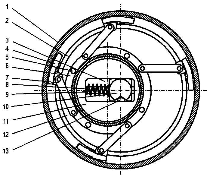
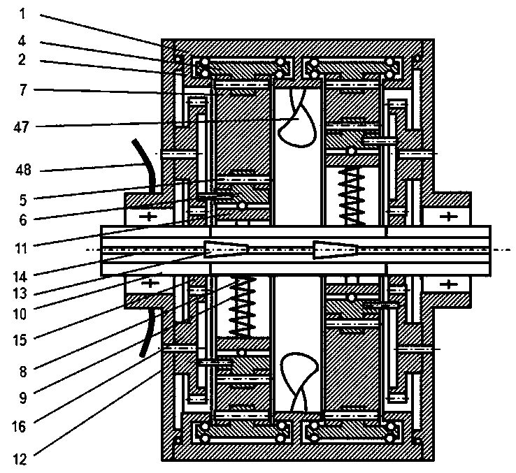
[0026] refer to figure 1 with figure 2 (If there is no additional specific reference to the legend in this paragraph in the same sentence, all refer to figure 1 with figure 2 ), the present invention includes a pulsating mechanism, an overrunning clutch mechanism, a transmission mechanism and a speed regulating mechanism. There is an eccentric wheel 11 in the pulsating mechanism, which is slidably connected with the power input shaft 10 for driving it through the radial chute 3 provided in its center But can not be in relative rotation, there is back-moving spring 9 between chute 3 and eccentric wheel 11, slide bar 8 is set in chute 3 and is slidably connected with input shaft 10, restricts the axial movement of eccentric wheel 11 and back-moving spring 9. When the eccentric wheel 11 rotates under the drive of the input shaft 10, its center revolves around the input shaft 10, and the centrifugal force is opposite to the force direction of the return spring 9, so that its e...
PUM
Abstract
The invention discloses a multi-phase common rail impulsing continuously variable transmission. The multi-phase common rail impulsing continuously variable transmission is a mechanical continuously variable transmission which is simple and compact in structure, gentle in output, efficient in transmission and convenient to use, integrates a plurality of overrunning clutch mechanism units with different phases on a common motion rail and reduces occupation of axial space, an one-way locking unit and the common rail directly form an overrunning clutch device, and a complete overrunning clutch mechanism unit comprising components of an inner ring, an outer ring, a locking element and the like is replaced, so that the structure is simpler and more compact, the contradiction between the output quality and the structural complexity is effectively relieved, balanced distribution is adopted on the whole, a flexible part with lighter weight is adopted to be used as a transmission mechanism to reduce dynamic load influence, a weak link, namely an overrunning clutch mechanism, is arranged on an outer ring and adopts surface contact transmission so as to bear larger input torque, and the motionof overrunning stroke adopts a rolling or magnetic suspension mode to reduce resistance, and a phase distribution adjusting mechanism, an auxiliary speed change mechanism, a steering mechanism, a speed adjusting mechanism suitable for manual operation and a gear locking mechanism are arranged in a matching mode, so that the transmission efficiency and the output power are improved, the speed adjusting range is wider, the application field is wider, and the use is more convenient.
Description
technical field [0001] The invention relates to a pulse type continuously variable transmission. Background technique [0002] As a mechanical continuously variable transmission, the pulsating continuously variable transmission has a long history of development. Its transmission-output combination includes a pulsating mechanism, a transmission mechanism and an overrunning clutch mechanism. The overrunning clutch mechanism converts the bidirectional motion of the pulsating mechanism into The unidirectional drive of the load has simple structure, clear shift logic, constant power mechanical characteristics, wide shift range, and the minimum output speed can be zero. The advantages are obvious, but to reduce the pulsation, it is necessary to increase the phase of the transmission-output combination unit However, the current multi-phase pulsating continuously variable transmission products and related research are mainly based on the crank-connecting rod structure, and multiple ...
Claims
Application Information
Patent Timeline
Application Date:The date an application was filed.
Publication Date:The date a patent or application was officially published.
First Publication Date:The earliest publication date of a patent with the same application number.
Issue Date:Publication date of the patent grant document.
PCT Entry Date:The Entry date of PCT National Phase.
Estimated Expiry Date:The statutory expiry date of a patent right according to the Patent Law, and it is the longest term of protection that the patent right can achieve without the termination of the patent right due to other reasons(Term extension factor has been taken into account ).
Invalid Date:Actual expiry date is based on effective date or publication date of legal transaction data of invalid patent.