
hub motor

A hub motor and motor shaft technology, which is applied in the direction of motors, electric components, electric vehicles, etc., can solve the problems of poor heat dissipation airflow uniformity and poor heat dissipation effect, and achieve the effect of uniform heat dissipation and uniform heating

Active Publication Date: 2022-02-25
HENAN UNIV OF SCI & TECH
View PDF7 Cites 0 Cited by
  • Summary
  • Abstract
  • Description
  • Claims
  • Application Information

AI Technical Summary

Problems solved by technology

[0004] The purpose of the present invention is to provide a wheel hub motor, which is used to solve the technical problem of poor heat dissipation effect caused by poor heat dissipation airflow uniformity in the current air-cooled hub motor

Method used


Image

  • hub motor
  • hub motor
  • hub motor

Examples


specific Embodiment 1

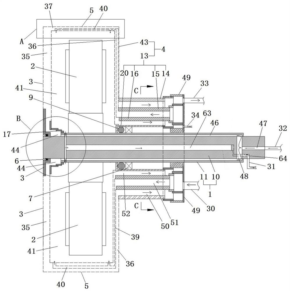
[0046] The in-wheel motor includes a motor shaft and a motor housing that rotates and cooperates with the motor shaft. A stator 2 is fitted and fixed on the motor shaft. The stator 2 is located in the motor housing, and a rotor is also fixed in the motor housing.

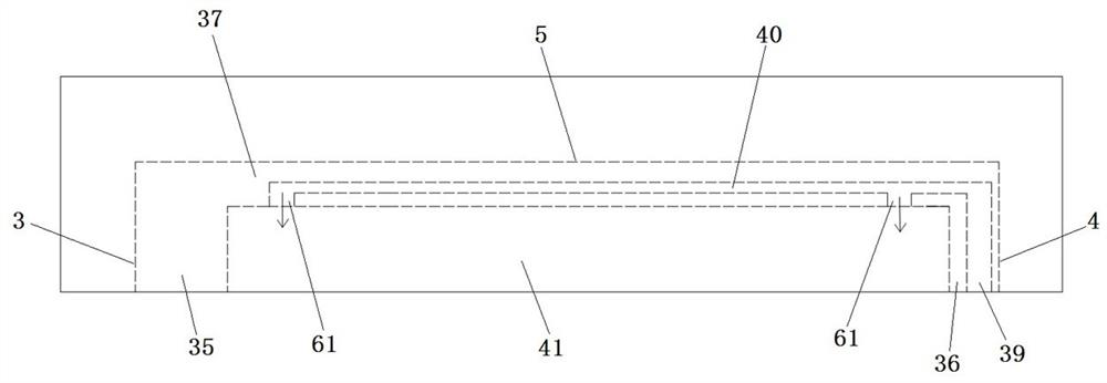
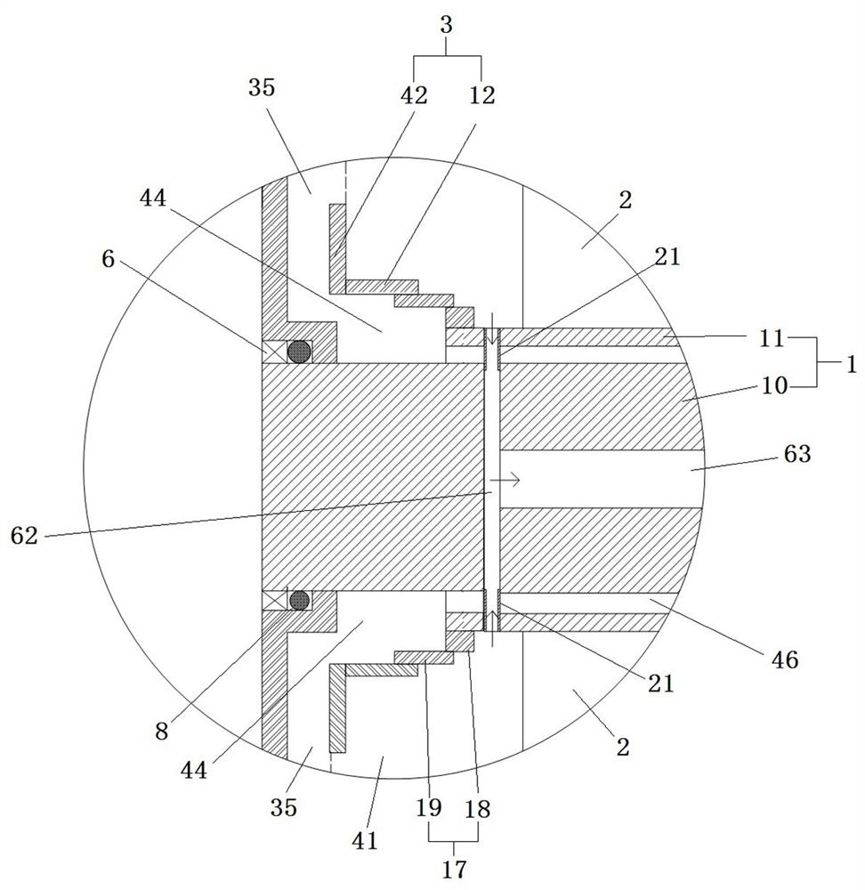
[0047] Such as Figure 1 to Figure 3 As shown, the housing includes an outer peripheral portion 5 and a shell end portion. The shell end portion extends radially along the motor shaft, and the outer peripheral portion extends circumferentially along the motor shaft. There are two shell end portions, namely the first shell end portion and the second shell end portion. The shell ends, the two shell ends are arranged at intervals in the axial direction of the motor, and surround with the outer peripheral part a housing cavity 41 for accommodating the stator 2 and the rotor. In this embodiment, the first shell end is arranged at the left end, and the second shell end is arranged at the right end.

[0048] The casing in...

specific Embodiment 2

[0072] The specific embodiment 2 of the in-wheel motor of the present invention, the difference between the in-wheel motor in this embodiment and the in-wheel motor in the specific embodiment 1 is that the deflector is directly hinged on the inner wall of the casing. In other embodiments, the deflector can also be hinged on the outer periphery of the casing.

specific Embodiment 3

[0073] The specific embodiment 3 of the hub motor of the present invention, the difference between the hub motor in this embodiment and the hub motor in the specific embodiment 1 is that the deflector is a V-shaped plate, and the V-shaped groove formed by the V-shaped plate faces the stator. , the V-shaped groove extends along the extension direction of the hinge axis of the deflector. In other embodiments, the deflector may also be a flat plate.

[0074] The specific embodiment 4 of the in-wheel motor of the present invention, the difference between the in-wheel motor in this embodiment and the in-wheel motor in the specific embodiment 1 is that in this embodiment, the hinge axis of the deflector is arranged parallel to the axis of the motor shaft at intervals. In other embodiments, the hinge axis of the deflector and the axis of the motor shaft may not be coplanar.


PUM


Abstract

The invention relates to a hub motor. The hub motor of the invention includes a motor shaft, a stator, a casing, a rotor, and a deflector. The deflector has a windward surface, and the windward surface is used to guide the airflow in the heat dissipation channel to blow to the heat-generating components in the casing. The heat-generating components in the casing dissipate heat, and the deflector is movably arranged on the casing. Compared with the way of direct ventilation in the prior art, the deflector of the present invention guides the airflow to the heat-generating components in the casing, which can improve the temperature of the machine. The heat-generating parts in the casing can dissipate heat better, and the deflector is movable on the casing. When the casing rotates, under the action of gravity, the posture of the deflector changes, changing the position where the airflow blows to the heating components in the casing, so that The heat-generating components in the casing are heated more evenly, so that the heat-dissipating airflow in the casing can evenly dissipate the heat-dissipating effect on the heat-generating components in the casing, which solves the poor heat dissipation effect caused by the poor uniformity of the internal heat-dissipating airflow in the current air-cooled hub motor question.

Description

technical field [0001] The present invention relates to hub motors. Background technique [0002] Due to the high power density, strong sealing and small space of the hub motor on the electric vehicle, the internal temperature of the hub motor rises rapidly and heat dissipation is difficult. Excessive temperature inside the hub motor will cause damage to the coil insulation and irreversible demagnetization of the permanent magnet, which will reduce the life of the hub motor. Therefore, the internal temperature of the hub motor must be controlled within the allowable range of the hub motor. [0003] The Chinese patent with the authorized announcement number CN204132322U and the authorized announcement date of 2018.07.03 discloses an air-cooled heat dissipation structure for an electric vehicle hub motor. There are hub motor end covers on the left and right sides of the hub motor, and the motor shaft and the left hub motor end Bearings are arranged between the covers, and the...

Claims


Application Information

Patent Timeline
Patent Type & Authority Patents(China)
IPC IPC(8): H02K5/20H02K9/02H02K9/19
CPCH02K5/20H02K9/02H02K9/19H02K2205/09Y02T10/64
Inventor 周志刚杨文豪李争争孟祥明
Owner HENAN UNIV OF SCI & TECH
Learn More