Bonding welding system and bonding welding method

A technology of welding system and welding method, which is applied in the field of hot-press welding, can solve the problems of long operation time for the staff to place the PCB board, affect the welding accuracy, and affect the processing efficiency, etc., so as to reduce the probability of glue flow, high work efficiency, and reduce the number of times The effect of product rate

Active Publication Date: 2020-06-19
信泰电子(西安)有限公司
View PDF23 Cites 0 Cited by
  • Summary
  • Abstract
  • Description
  • Claims
  • Application Information

AI Technical Summary

Problems solved by technology

[0004] The above-mentioned existing technical solutions have the following defects: when the PCB board is welded using the hot-press welding method, since the welding accuracy required by the PCB board is very high, the alignment work at the beginning of the welding is particularly important. It will affect the subsequent welding accuracy and lead to defective products, so the staff usually takes a long time to place the PCB board, which will affect the processing efficiency

Method used


Image

  • Bonding welding system and bonding welding method
  • Bonding welding system and bonding welding method
  • Bonding welding system and bonding welding method

Examples


Embodiment 1

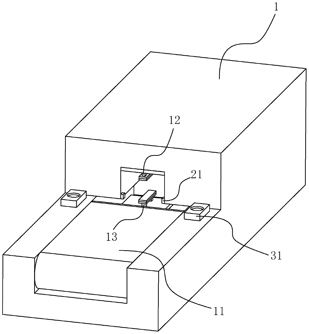
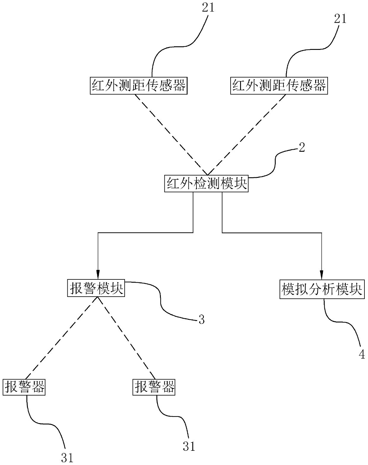
[0048] Embodiment one: a kind of bonding welding system, such as figure 1 As shown, a thermocompression welding device 1 is included, and a feeding conveyor belt 11 is connected to the feed port of the thermocompression welding device 1 . Two infrared range-finding sensors 21 are fixedly connected to the position of the thermocompression welding equipment 1 close to the feeding conveyor belt 11. It is arranged along the conveying direction of the feeding conveyor belt 11. The distance between the two infrared ranging sensors 21 is equal to the width of the workpiece.

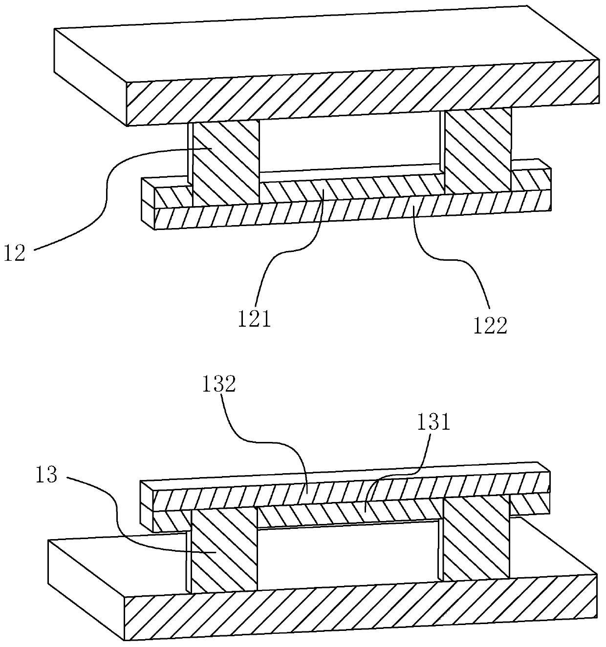
[0049] Such as figure 1 and figure 2As shown, the thermocompression welding equipment 1 includes an upper welding head 12 and a lower welding head 13 . An upper pressing plate 121 is fixedly connected to the upper welding head 12 , and a lower pressing plate 131 is fixedly connected to the lower welding head 13 . The upper platen 121 is fixedly connected with an upper high temperature resistant Teflon 122 ...

Embodiment 2

[0052] Embodiment two: a kind of bonding welding method, concrete steps are as follows:

[0053] Step 1. Install two infrared distance measuring sensors 21 near the feeding conveyor belt 11 in the thermocompression welding equipment 1, so that the infrared light emitted by the two infrared distance measuring sensors 21 is parallel and the distance is equal to the width of the workpiece.

[0054] Step 2, the staff places the workpiece on the feeding conveyor belt 11, and makes two infrared rays pass along both sides of the workpiece as much as possible.

[0055] Step 3: If the position of the workpiece is incorrect, the two alarms 31 on the thermocompression welding equipment 1 will send out an alarm according to which side the workpiece is deflected to. Workers adjust the position of the workpiece. If the position of the workpiece is correct, the staff starts the feeding conveyor belt 11 and the thermocompression welding equipment 1 to weld the workpiece. It can make it easi...


PUM


Abstract

The invention discloses a bonding welding system and a bonding welding method, and belong to the technical field of thermocompression welding. The bonding welding system comprise thermocompression welding equipment, wherein a feeding conveying belt is connected to a feeding port of the thermocompression welding equipment, and two infrared distance measuring sensors are fixedly connected to the position, close to the feeding conveying belt, of the thermocompression welding equipment; two infrared emitters are located on the two sides of the feeding conveying belt, the impact directions of the two infrared distance measuring sensors are arranged in the conveying direction of the feeding conveying belt, the distance between the two infrared distance measuring sensors is equal to the width ofa workpiece, the thermocompression welding equipment is connected with a control system, and the control system comprises an infrared detection module and an alarm module, when infrared rays emitted by the infrared distance measuring sensors are blocked, electric signals are transmitted to the infrared detection module, the infrared detection module sends the electric signals to the alarm module,and the alarm module gives an alarm after receiving the electric signals. The bonding welding system and the bonding welding method have the effects that a worker can conveniently and rapidly place the workpiece, and the working efficiency is effectively improved.

Description

technical field [0001] The invention relates to the technical field of thermocompression welding, in particular to a bonding welding system and a welding method. Background technique [0002] At present, bonding welding is also called thermocompression welding. Thermocompression welding is a welding process for connecting flexible circuit boards and rigid circuit boards. As an emerging manufacturing process and an important part of microelectronic surface assembly technology, stable and efficient thermocompression welding Craftsmanship is undoubtedly an important link to ensure the good quality of products. [0003] The prior art can refer to the Chinese invention patent whose application publication number is CN107755838A, which discloses a thermocompression welding device, including a working platform, a lifting device, a thermocompression welding head, and a welding head for sending tin wire to the thermocompression welding head. The position of the tin feeding device, t...

Claims


Application Information

Patent Timeline
Patent Type & Authority Applications(China)
IPC IPC(8): B23K20/02B23K20/26
CPCB23K20/023B23K20/26
Inventor 王振鹏何岩飞蔡景灵周俊杰
Owner 信泰电子(西安)有限公司
Why Eureka
Try Eureka