Motor shell drawing part surface finishing treatment process

A technology for surface finishing and processing technology, applied in the field of surface finishing processing technology of motor casing drawing parts, can solve the problems of high grinding precision, low grinding efficiency, difficult to guarantee, etc., to improve grinding speed, reduce grinding efficiency, reduce wear effect

Active Publication Date: 2020-06-19
深圳市可高机电有限公司
View PDF11 Cites 7 Cited by
  • Summary
  • Abstract
  • Description
  • Claims
  • Application Information

AI Technical Summary

Problems solved by technology

[0006] Aiming at the problems in the prior art, the purpose of the present invention is to provide a surface finishing treatment process of the stretched part of the motor casing, which solves the problem that the wheel width of the surface of the motor casing is too large during finishing grinding. Grinding requires multiple clamping. For example, secondary clamping is required when grinding the outer surface of the motor and the inner wall of the round hole of the motor casing. The secondary clamping makes the grinding efficiency low, and it is difficult to ensure high grinding in mass production. Technical issues with precision

Method used


Image

  • Motor shell drawing part surface finishing treatment process
  • Motor shell drawing part surface finishing treatment process
  • Motor shell drawing part surface finishing treatment process

Examples


Embodiment Construction

[0038] The embodiments of the present invention will be described in detail below with reference to the accompanying drawings, but the present invention can be implemented in many different ways defined and covered by the claims.

[0039] In order to make the technical means, creative features, goals and effects achieved by the present invention easy to understand, the present invention will be further described below in conjunction with specific illustrations.

[0040] It should be noted that when an element is said to be "fixed" to another element, it may be on the other element or there may be an intervening element. When an element is referred to as being "connected to" another element, it can be directly connected to the other element or intervening elements may also be present. The terms "vertical", "horizontal", "left", "right" and similar expressions are used herein for the purpose of illustration only and do not represent the only embodiment.

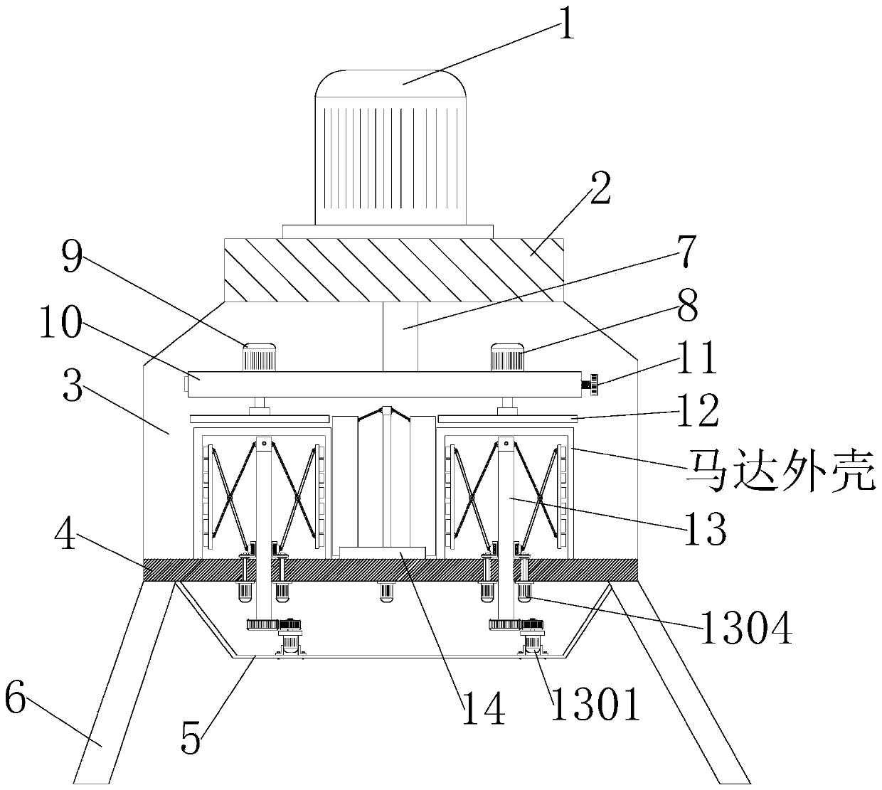
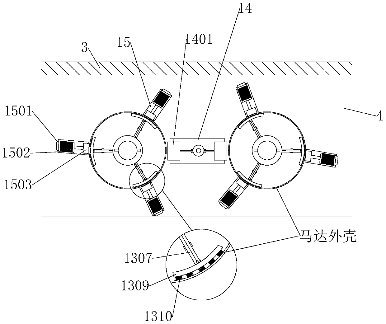
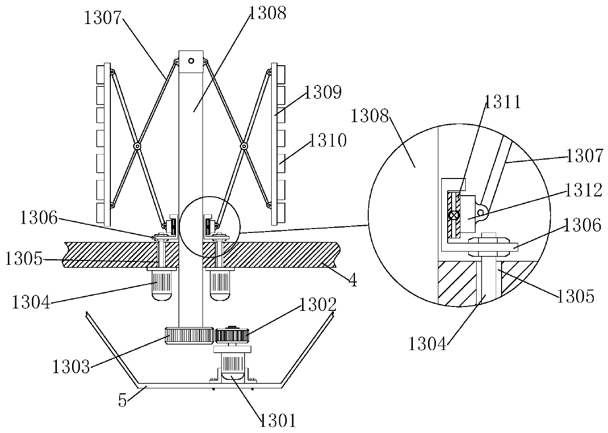
[0041] see Figure 1-...


PUM


Abstract

The invention discloses a motor shell drawing part surface finishing treatment process and relates to the technical field of machining. A motor shell drawing part surface finishing treatment device isadopted to finish the motor shell drawing part surface finishing treatment process in a cooperative manner and comprises a bottom support plate horizontally placed, wherein a support ribbed plate erected at the top end of the bottom support plate is arranged at the top end of the bottom support plate; a top support plate horizontally fixed is arranged at the top end of the support ribbed plate; and a hydraulic cylinder is mounted at the top end of the top support plate. a cutting edge is mounted at the top end of an outer polishing block; when the outer polishing block polishes the inner wallof a motor shell, the cutting edge can scrape a projecting object on the inner wall of the motor shell to increase the polishing speed; and scraped chippings can be conveniently collected in a chipping falling groove 1408, so that the situation that the scraped chippings fall into a polishing surface to scratch the inner wall of the motor shell is avoided.

Description

technical field [0001] The invention relates to the technical field of mechanical processing, in particular to a surface finishing treatment process of a stretched part of a motor casing. Background technique [0002] The motor housing is a necessary component and relative positional relationship for protecting and fixing the normal operation of the motor. It is a housing-like device. The motor housing is usually cylindrical, square and oval. , In order to facilitate processing, the motor casing is often made into a cylindrical shape. [0003] Existing, patent No. CN201721343736.4 discloses an explosion-proof motor casing grinding table, including a concave operating table, a rectangular operating table and a bottom plate, a motor is embedded in the middle of the side groove wall of the concave operating table, and the output end of the motor The coupling is connected to one end of the rotating shaft, and the two ends of the groove wall on one side of the concave operation ...

Claims


Application Information

Patent Timeline
IPC IPC(8): B24B5/01B24B41/06B24B5/04B24B5/36B24B5/35B24B55/06B24B47/08B23D79/02B23P15/00
CPCB23D79/02B23P15/00B24B5/01B24B5/045B24B5/047B24B5/35B24B5/363B24B41/067B24B47/08B24B55/06
Inventor 高峰王彦洲
Owner 深圳市可高机电有限公司
Why Eureka
Try Eureka