Yarn winding device and yarn winding process

A winding device and yarn technology, which is applied in the directions of transportation and packaging, delivery of filamentous materials, thin material processing, etc., can solve the problem of yarn unraveling, reduce the precision of yarn winding operation, and affect yarn processing Efficiency and other issues to achieve the effect of ensuring tightness, ensuring that it will not scatter, and improving precision

Inactive Publication Date: 2020-06-19
尹梦雅
View PDF0 Cites 5 Cited by
  • Summary
  • Abstract
  • Description
  • Claims
  • Application Information

AI Technical Summary

Problems solved by technology

[0002] Yarn is a kind of textile, which is processed into products of a certain fineness with various textile fibers. It is used for weaving, rope making, thread making, knitting and embroidery, etc. In the process of processing, different processing needs to be carried out according to the specific usage conditions. No matter what kind of situation the yarn is used in, it needs to be wound into a tube to facilitate the delivery and management of the yarn. However, the existing yarn winding operation The following problems exist in: a. The traditional yarn winding method cannot guarantee the tension in the yarn winding operation, which will easily lead to the fluffy inside of the yarn after winding, which will affect the stability of the yarn after winding into a bobbin , it is easy to cause the yarn to scatter, which reduces the precision of the yarn winding operation. b. In the traditional yarn winding operation, multiple yarn bobbins cannot be wound at the same time, and the replacement and fixing of the yarn bobbins The process is cumbersome and affects the efficiency of yarn processing

Method used


Image

  • Yarn winding device and yarn winding process
  • Yarn winding device and yarn winding process
  • Yarn winding device and yarn winding process

Examples


Embodiment Construction

[0028] The implementation of the present invention will be described in detail below with reference to the drawings and examples, so as to fully understand and implement the implementation process of how to use technical means to solve technical problems and achieve technical effects in the present invention.

[0029] In addition, the following terms are defined based on the functions in the present invention, and may be different according to the user's or operator's intention or practice. Therefore, these terms are defined based on the entire content of this specification.

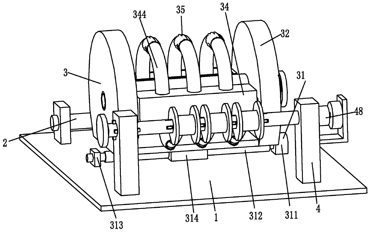
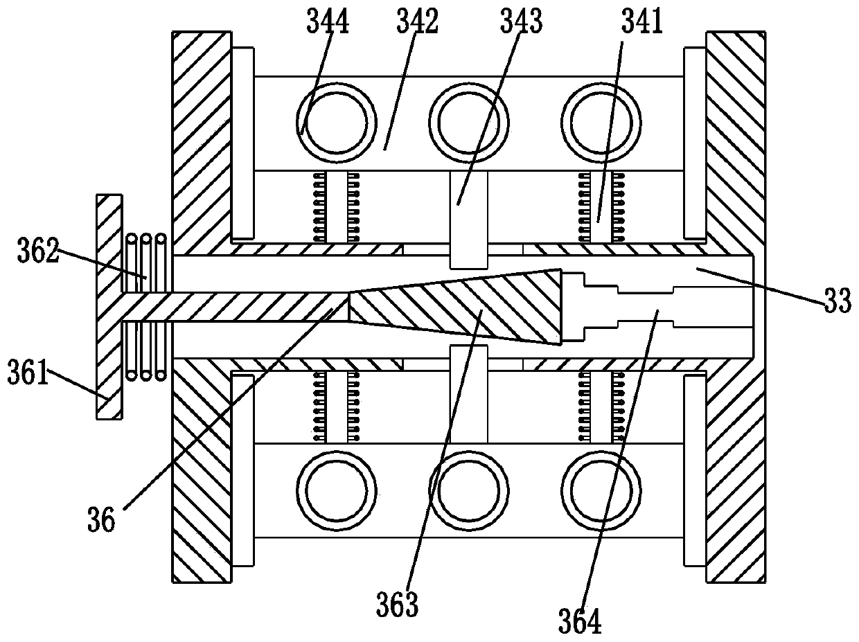
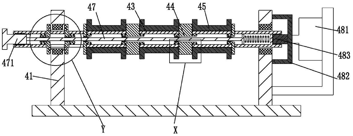
[0030] Such as Figure 1 to Figure 5 As shown, a yarn winding device includes a bottom plate 1, on which a winding roller 2, a tensioning device 3 and a winding device 4 are sequentially arranged from back to front;

[0031] The yarn goes around the winding roller 2 and is connected to the tensioning device 3 , and the yarn is wound on the winding device 4 after being stretched by the tensioning device ...


PUM


Abstract

The invention relates to a yarn winding device and a yarn winding process. The yarn winding device comprises a bottom plate. A winding roller, a tensioning device and a winding device are sequentiallyarranged on the bottom plate from back to front. The yarn winding device and the yarn winding process can solve the following problems in an existing yarn winding operation: a, by means of a traditional yarn winding mode, the tensioning force in the yarn winding operation cannot be guaranteed, the fluffy interiors of the wound yarns are caused easily, the stability of the yarns wound into rolls is influenced, the yarns are easily scattered, and the degree of precision of the yarn winding operation is reduced; and b, in the traditional operation of winding the yarns into the rolls, multiple yarn rolls cannot be wound at the same time, replacement of the yarn rolls and fixed processes are tedious, and the processing efficiency of the yarns is influenced.

Description

technical field [0001] The invention relates to the technical field of textile processing machinery, in particular to a yarn winding device and a yarn winding process. Background technique [0002] Yarn is a kind of textile, which is processed into products of a certain fineness with various textile fibers. It is used for weaving, rope making, thread making, knitting and embroidery, etc. In the process of processing, different processing needs to be carried out according to the specific usage conditions. No matter what kind of situation the yarn is used in, it needs to be wound into a tube to facilitate the delivery and management of the yarn. However, the existing yarn winding operation The following problems exist in: a. The traditional yarn winding method cannot guarantee the tension in the yarn winding operation, which will easily lead to the fluffy inside of the yarn after winding, which will affect the stability of the yarn after winding into a bobbin , it is easy to ...

Claims


Application Information

Patent Timeline
Patent Type & Authority Applications(China)
IPC IPC(8): B65H54/40B65H59/10
CPCB65H54/40B65H59/10
Inventor 尹梦雅
Owner 尹梦雅
Why Eureka
Try Eureka