Pile hammer of a building construction punching pile driver

A technology for building construction and pile driver, which is applied to drill pipes, casings, drill pipes, etc., can solve the problems that the hammer head is easy to get stuck in the hole, the plum blossom hole is easy to appear, and the hammer head pile hole is inclined, etc., and the structure is ingenious, Avoid the deflection of the hammer head and reduce the effect of collapsed holes

Active Publication Date: 2021-06-15
NORTH CHINA UNIV OF WATER RESOURCES & ELECTRIC POWER
View PDF0 Cites 0 Cited by
  • Summary
  • Abstract
  • Description
  • Claims
  • Application Information

AI Technical Summary

Problems solved by technology

[0004] In view of the above situation, in order to overcome the defects of the prior art, the present invention provides a pile hammer of a construction punching pile driver, which effectively solves the problem that the hammer head of the existing punching pile driver is prone to pile hole inclination, and the hammer head is easy to tilt. Stuck in the hole, prone to plum blossom holes, prone to collapse holes

Method used


Image

  • Pile hammer of a building construction punching pile driver
  • Pile hammer of a building construction punching pile driver
  • Pile hammer of a building construction punching pile driver

Examples


Embodiment 2

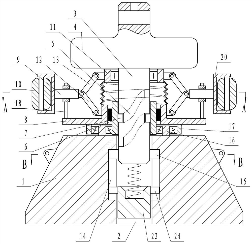
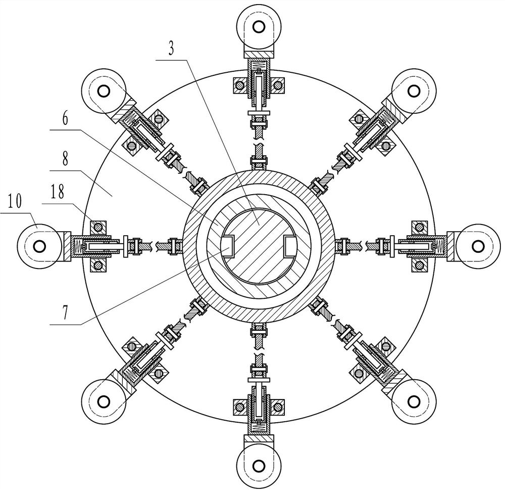
[0021] Embodiment 2, on the basis of Embodiment 1, in order to realize that the roller 10 can compact the hole wall during punching to prevent the hole from collapsing, the inner side of the annular plate 8 has an annular protrusion, and the telescopic rod 9 is close to the central axis 3 One end and the annular projection on the annular plate 8 are hinged together through the first connecting rod 12, the central shaft 3 is covered with a rotatable annular sleeve 11, and the end of the telescopic rod 9 near the central axis 3 is connected to the annular sleeve 11 through the second The connecting rod 13 is hinged, and the first connecting rod 12 and the second connecting rod 13 form a V shape with an opening inward. When the central shaft 3 moves downward to drive the annular sleeve 11 to move downward, the first connecting rod 12 and the second connecting rod 13 can push the roller 10 to move to the side away from the central axis 3 through the telescopic rod 9 and compact the...

Embodiment 3

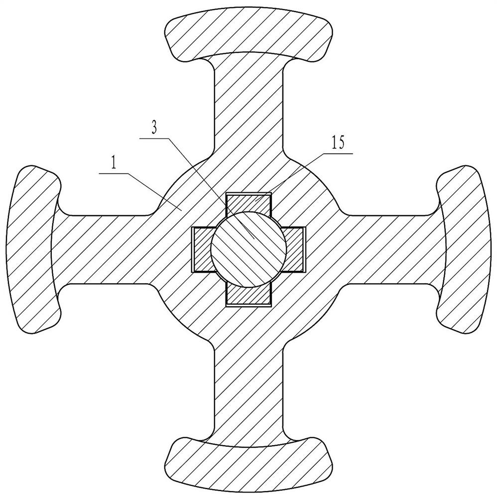
[0022] Embodiment 3, on the basis of Embodiment 1, in order to realize that the central axis 3 can move up and down along the central hole 2 but cannot rotate, the inner wall of the central hole 2 is provided with a plurality of vertical grooves 14 uniformly distributed around the circumference. The lower end of the central shaft 3 is fixed with a plurality of first protruding blocks 15 corresponding to the vertical grooves 14 one by one. The first protruding blocks 15 are placed in the vertical grooves 14 and can move up and down along the vertical grooves 14. The vertical grooves 14 are located in the center. The middle part of the hole 2 and the upper and lower ends of the vertical groove 14 are not connected, so that the first protruding piece 15 does not separate from the vertical groove 14 .

Embodiment 4

[0023] Embodiment 4, on the basis of Embodiment 1, in order to realize that the cylinder 6 can drive the ring plate 8 to rotate in one direction, a one-way clutch is installed between the cylinder 6 and the ring plate 8 .


PUM


Abstract

The invention provides a pile hammer of a construction punching pile driver, which effectively solves the problem that the hammer head of the existing punching pile driver is prone to inclination of the pile hole, the hammer head is easy to be stuck in the hole, and the plum blossom hole is easy to appear. The problem of hole collapse; the technical solution is to include the main body of the hammer head of the punching pile driver, the center of the main body has a central hole, the central hole has a central shaft, the upper end of the central shaft has a counterweight, and there is a groove on the central shaft. There is a cylinder on the central axis, a slider on the inner wall of the cylinder, an annular plate is set on the cylinder, and a telescopic rod is arranged on the annular plate, which can drive the telescopic rod to rotate, and a cylinder is installed on the end of the telescopic rod away from the central axis. shaped roller, and the central shaft is fitted with a rotatable annular sleeve; the invention has an ingenious structure, which can also compact the side wall of the pile hole to build the wall during the punching process, reducing the occurrence of hole collapse and effectively avoiding the hammer The head is deflected to prevent the hammer head from being stuck in the pile hole, realize punching and reaming, and improve the bearing capacity of the pile foundation.

Description

technical field [0001] The invention relates to the technical field of construction machinery, in particular to a pile hammer of a construction punching pile driver. Background technique [0002] In bridge construction, early piling is very important for the stability and safety of the bridge. Bridge piling is a construction method in which piles of various materials are driven, pressed, vibrated or screwed into the foundation soil with special machines. Commonly used hammering method, vibration method, water jet method and pile pressing method. Among them, the hammering method is to use the impact energy of the pile hammer to overcome the resistance of the foundation soil to the pile, and drive the pile to a predetermined depth, which is suitable for soft plastic or plastic cohesive soil layers. The main equipment used are pile frame, pile hammer, power equipment and so on. [0003] During the construction process, the pile hammer hammers the ground. During repeated hamm...

Claims


Application Information

Patent Timeline
Patent Type & Authority Patents(China)
IPC IPC(8): E21B10/36E21B10/26E21B17/10
CPCE21B10/26E21B10/36E21B17/1057
Inventor 张敏李列列韩瑞聪姚贤华
Owner NORTH CHINA UNIV OF WATER RESOURCES & ELECTRIC POWER
Why Eureka
Try Eureka