
An automatic tight packing polished rod sealer

A polished rod sealer and packing technology, used in sealing/packing, wellbore/well components, earth-moving drilling, etc. Achieve the effect of low manufacturing cost, avoid excessive wear and good sealing performance

Active Publication Date: 2021-01-26
江天科技有限公司
View PDF6 Cites 2 Cited by
  • Summary
  • Abstract
  • Description
  • Claims
  • Application Information

AI Technical Summary

Problems solved by technology

[0003] Ordinary polished rod sealers use threaded packing caps to directly compress the packing. In order to prevent the packing from leaking, additional pre-tightening force will be added when compressing the packing. Excessive pre-tightening force will aggravate the packing wear, reducing packing life
The packing is a wearing part. After 2 to 3 days of use, the operator must go to the well to rotate the packing cap to press the packing down and continue pumping. Otherwise, oil leakage will occur. The work is frequent and extremely Greatly increases the operating cost; since the compaction of the packing is controlled by the operator, when the packing is worn out, the packing cannot be compacted in time, posing a safety hazard

Method used


Image

  • An automatic tight packing polished rod sealer
  • An automatic tight packing polished rod sealer
  • An automatic tight packing polished rod sealer

Examples


Embodiment 1

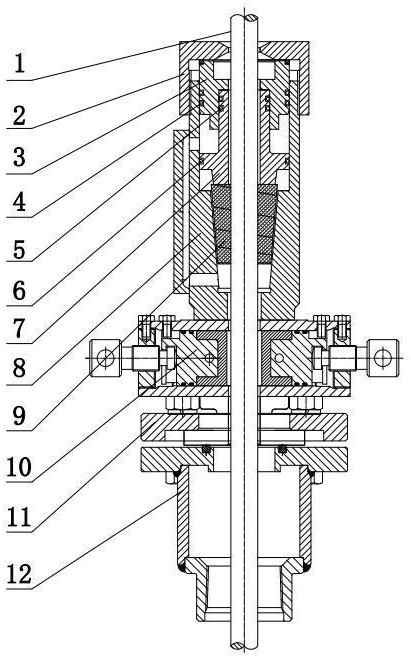
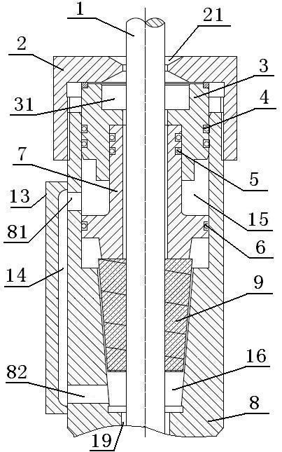
[0028] Such as figure 1 and figure 2 As shown, an automatic tight-packing polished rod sealer is mainly composed of a lower joint 12, a deflection adjustment mechanism 11, an auxiliary sealing mechanism 10, a packing box 8 and a packing pressing cap 2 which are sequentially set on the polished rod 1. The root box 8 and the packing pressing cap 2 are threadedly connected, wherein the auxiliary sealing mechanism 10, the deflection adjustment mechanism 11 and the lower joint 12 below the packing box 8 are all existing components. The auxiliary sealing mechanism 10 is mainly used to cut off the pressure oil under the packing 9 when the packing 9 needs to be replaced, and the deviation adjustment mechanism 11 is mainly used to prevent the polished rod 1 from eccentrically grinding the seal of the polished rod sealer, and the sealing of the polished rod sealer The component refers to the packing 9 in this embodiment, and the lower joint 12 is connected with the well head of the oi...

Embodiment 2

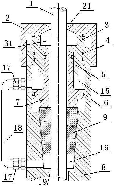
[0035] An automatic tight packing polished rod sealer. The difference between this embodiment and the first embodiment is that the lower through hole 82 and the upper through hole 81 are connected through the connecting pipe 18, and the connecting pipe 18 can be a hydraulic rubber hose, etc., and the connecting pipe 18 The two ends of each are respectively connected with the lower through hole 82 and the upper through hole 81 through joints. By adopting the above solution, the structure is simple, the manufacture is convenient, and the layout of the lower through hole 82 and the upper through hole 81 is not limited.


PUM


Abstract

The embodiment of the invention discloses an automatic tight packing polished rod sealer, which belongs to the technical field of oil production equipment in oilfields. It includes a packing gland and a packing box connected to the packing gland. Inside the packing box, there are packing, hydraulic piston and piston gland; the piston gland, hydraulic piston and packing box together form an upper sealing oil A lower sealing oil cavity is provided inside the packing box below the packing, and the pressure oil in the oil well flows into the lower sealing oil cavity and the upper sealing oil cavity through the gap in turn. The invention conveniently realizes that the pressure oil in the lower sealing oil cavity is introduced into the upper sealing oil cavity, and the pressure oil directly acts on the upper surface of the hydraulic piston, and the hydraulic piston automatically pressurizes and seals the packing under the action of the pressure oil, It avoids the excessive wear on the packing usually caused by manually increasing the pre-tightening force, improves the service life of the packing, has a simple structure, low processing and manufacturing costs, and is safe and reliable.

Description

technical field [0001] The invention relates to the technical field of oil production equipment in oilfields, in particular to a polished rod sealer for automatic tight packing. Background technique [0002] At present, during oil pumping operations of oil pumping units in oil fields, it is necessary to use packing to seal the polished rod performing reciprocating pumping motion. When the packing wears and leaks, it is necessary to manually compress the packing to prevent leakage. [0003] Ordinary polished rod sealers use threaded packing caps to directly compress the packing. In order to prevent the packing from leaking, additional pre-tightening force will be added when compressing the packing. Excessive pre-tightening force will aggravate the packing wear and reduce the life of the packing. The packing is a wearing part. After 2 to 3 days of use, the operator must go to the well to rotate the packing cap to press the packing down and continue pumping. Otherwise, oil le...

Claims


Application Information

Patent Timeline
Patent Type & Authority Patents(China)
IPC IPC(8): E21B33/03
CPCE21B33/03
Inventor 刘兵吕振超李国鹏夏明周鲁斌翟伟强姜兆锐魏继允
Owner 江天科技有限公司
Learn More