


Quick Research
Generate reliable direction feasibility study reports for your R&D in just a few steps.

Technical Q&A
Discover and master advanced knowledge NOW. Basics, ideas, possibilities, all at once.

Find Solutions
As an expert in R&D theories, this can generate solutions to your technical problems instantly.

Evaluate Feasibility
Analyze your overall solution with one click, know your potential R&D risks in advance.

Monitor Landscape
Get weekly tech updates, stay abreast of the latest tech innovations and key insights.
Tester for single-ended connected twisted pair crosstalk hunting of cable
A tester, single-ended technology, applied in the direction of continuity test, electrical connection test, instrument, etc., can solve the problems of reducing the work efficiency of testers and cumbersome test steps, and achieve the effect of saving time and cost and improving work efficiency
- Summary
- Abstract
- Description
- Claims
- Application Information
AI Technical Summary
Problems solved by technology
Method used
Image

Examples
Embodiment 1
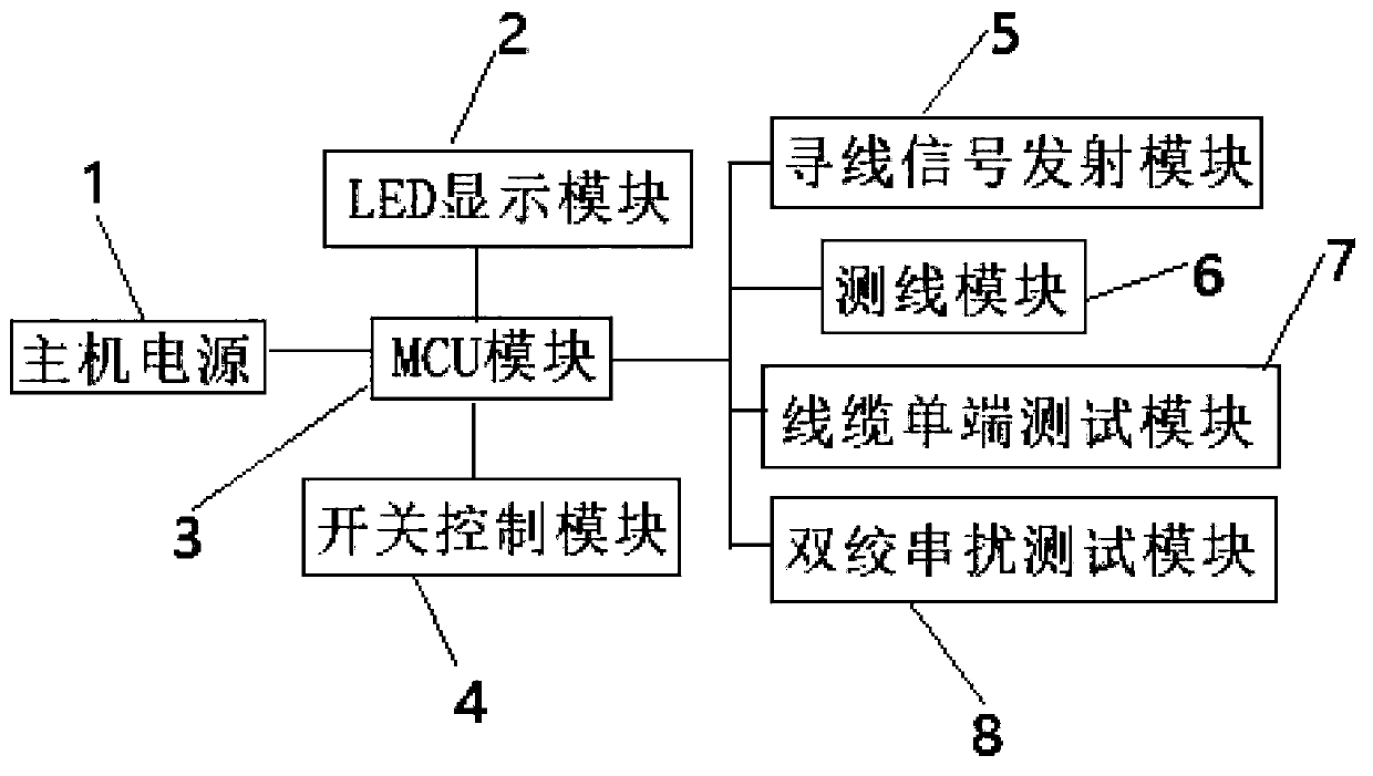
[0059] like Figure 12-15 Shown is a schematic diagram of Embodiment 1 of the present invention, including an MCU module, a cable single-ended test module, a power module and a display module diagram. The MCU module controls the cable single-end test module, and displays the result to the display module. The power module is electrically connected with the MCU module for providing power.
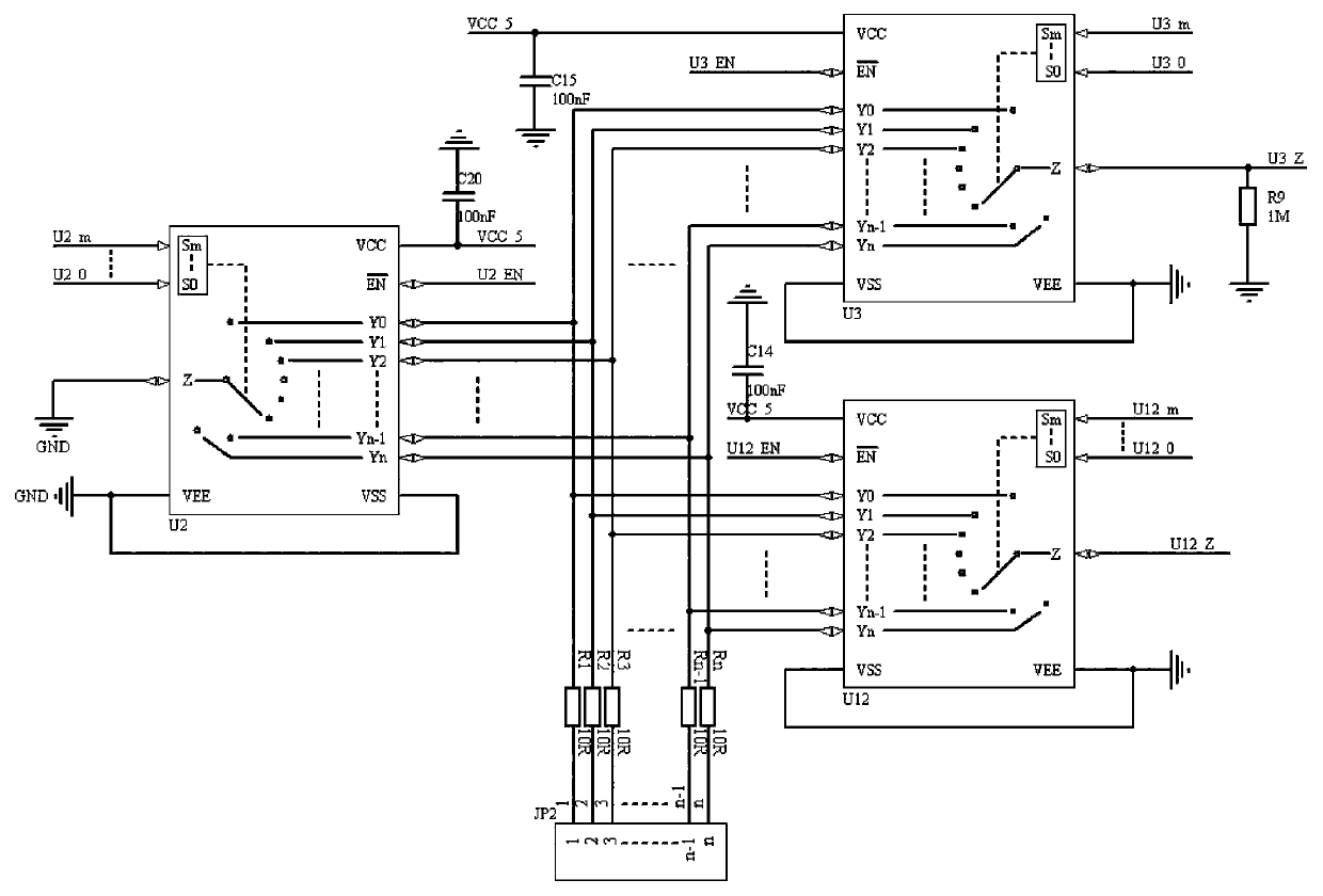
[0060] The operating principle of the cable single-ended test module:
[0061]1. Initialization: Due to the interference of PCB wiring and electronic components, when the cable is not connected, there is a parasitic capacitance C1 inside, which needs to be initialized first to eliminate the influence of parasitic capacitance on the test. Do not connect any cables, take the first core of JP2 as an example, the micro-control chip sets the 17th pin U1_28 to low level, and controls U3 to open; the micro-control chip sets the 18th pin U12_Z to high level ;The micro-control chip sets the 12th pi...
Embodiment 2
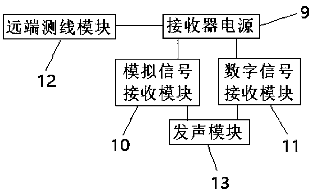
[0065] like Figure 16-20 As shown, it is a schematic diagram of Embodiment 2 of the present invention, including an MCU module, a cable single-end test module, a line hunting module, a line measuring module and a display module. The MCU module controls the cable single-end testing module, the hunting module and the testing module, and displays the results to the display module.
[0066] The principle of the measuring line module is the same as that of the existing line measuring instrument.
[0067] The MCU module is connected with a hunting module, and its working principle is: the sound signal sent by the hunting signal oscillating sounder is connected to the port of the target cable through the RJ45 / RJ11 universal interface, so that a surrounding loop is generated around the target cable loop. For the sound signal field, use a high-sensitivity inductive line finder to quickly identify the signal field it sends out along the way and at the end of the loop, so as to find th...
PUM
 Abstract
Description
Claims
Application Information
 - R&D Engineer
- R&D Manager
- IP Professional
- Industry Leading Data Capabilities
- Powerful AI technology
- Patent DNA Extraction
Browse by: Latest US Patents, China's latest patents, Technical Efficacy Thesaurus, Application Domain, Technology Topic, Popular Technical Reports.
© 2024 PatSnap. All rights reserved.Legal|Privacy policy|Modern Slavery Act Transparency Statement|Sitemap|About US| Contact US: help@patsnap.com