Permanent magnet coupler with variable magnet position and variable speed

A coupling and magnet technology, applied in the field of permanent magnet couplings, can solve the problems of bloated structure, unfavorable product promotion and application, large adjustment workload, etc., and achieve the effects of being beneficial to popularization and application, convenient and quick adjustment, and strong application adaptability.

Pending Publication Date: 2020-06-19
DATANG LINZHOU THERMAL POWER CO LTD
View PDF1 Cites 3 Cited by
  • Summary
  • Abstract
  • Description
  • Claims
  • Application Information

AI Technical Summary

Problems solved by technology

The structure of the above scheme is too bloated and relatively complicated, which indirectly increases the cost
[0006] The existing variable speed permanent magnet coupling needs to manually disassemble the bolts and gaskets to change the air gap, thereby changing the transmission torque and output speed, and the adjustment workload is large and time-consuming
These problems lead to low user acceptance, which is not conducive to the promotion and application of products

Method used


Image

  • Permanent magnet coupler with variable magnet position and variable speed
  • Permanent magnet coupler with variable magnet position and variable speed
  • Permanent magnet coupler with variable magnet position and variable speed

Examples


Embodiment 1

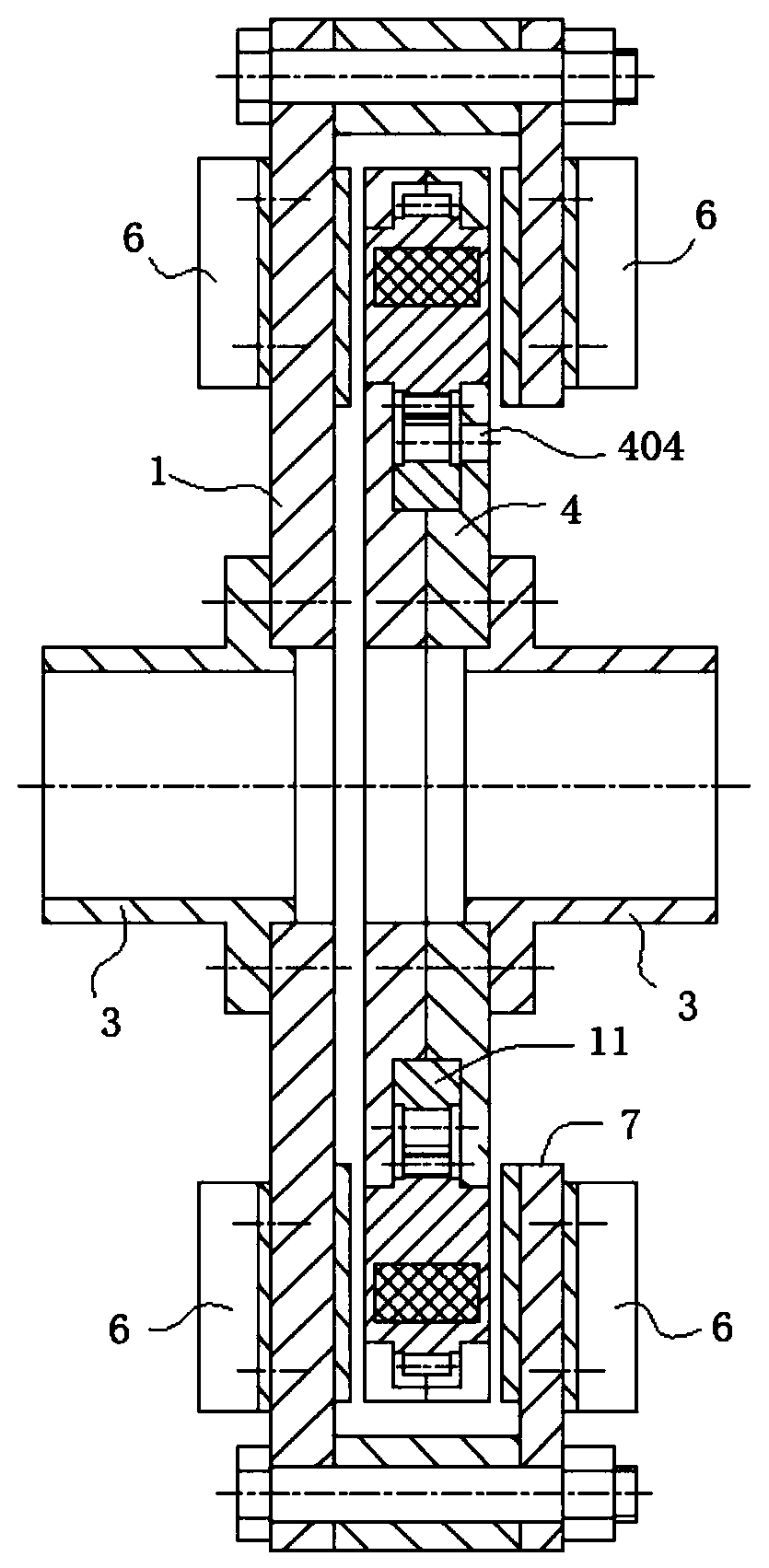
[0044] see figure 1 As shown, the present invention is a permanent magnet coupling with variable magnet position and speed, including a conductor rotor assembly installed at the drive end of the permanent magnet coupling; and a permanent magnet rotor assembly installed at the load end of the permanent magnet coupling.

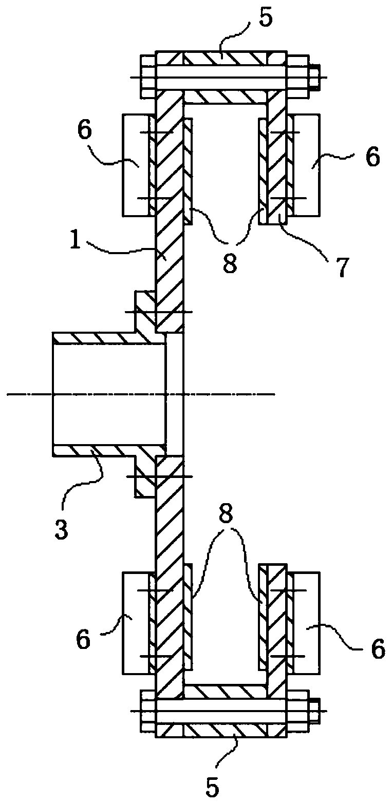
[0045] see figure 2As shown, the conductor rotor assembly includes a first conductor disk 1 and a second conductor disk 7, and the outer edge of the first conductor disk 1 is connected to the outer edge of the second conductor disk 7 through a connecting piece; the connecting piece includes a spacer 5 and a bolt assembly, and the spacer The cylinder 5 is located between the first conductor disk 1 and the second conductor disk 7, and is fixed by a bolt assembly, so that there is a certain distance between the first conductor disk 1 and the second conductor disk 7, which is used for clearance fit with the permanent magnet rotor assembly .

[0046] A fixing mem...

Embodiment 2

[0054] see figure 1 As shown, the present invention is a permanent magnet coupling with variable magnet position and speed, including a conductor rotor assembly installed at the drive end of the permanent magnet coupling; and a permanent magnet rotor assembly installed at the load end of the permanent magnet coupling.

[0055] see figure 2 As shown, the conductor rotor assembly includes a first conductor disk 1 and a second conductor disk 7, and the outer edge of the first conductor disk 1 is connected to the outer edge of the second conductor disk 7 through a connecting piece; the connecting piece includes a spacer 5 and a bolt assembly, and the spacer The cylinder 5 is located between the first conductor disk 1 and the second conductor disk 7, and is fixed by a bolt assembly, so that there is a certain distance between the first conductor disk 1 and the second conductor disk 7, which is used for clearance fit with the permanent magnet rotor assembly .

[0056] A fixing me...

Embodiment 3

[0064] see figure 1 As shown, the present invention is a permanent magnet coupling with variable magnet position and speed, including a conductor rotor assembly installed at the drive end of the permanent magnet coupling; and a permanent magnet rotor assembly installed at the load end of the permanent magnet coupling.

[0065] see figure 2 As shown, the conductor rotor assembly includes a first conductor disk 1 and a second conductor disk 7, and the outer edge of the first conductor disk 1 is connected to the outer edge of the second conductor disk 7 through a connecting piece; the connecting piece includes a spacer 5 and a bolt assembly, and the spacer The cylinder 5 is located between the first conductor disk 1 and the second conductor disk 7, and is fixed by a bolt assembly, so that there is a certain distance between the first conductor disk 1 and the second conductor disk 7, which is used for clearance fit with the permanent magnet rotor assembly .

[0066] A fixing me...


PUM


Abstract

The invention discloses a permanent magnet coupler with a variable magnet position and a variable speed, and relates to the technical field of permanent magnet eddy current transmission. The permanentmagnet coupler comprises a permanent magnet rotor assembly installed at the load end of a permanent magnet coupler. The permanent magnet rotor assembly is located between a first conductor disc and asecond conductor disc. The permanent magnet rotor assembly comprises a first rotor disc and a second rotor disc which are oppositely and coaxially matched; a coaxial gear ring and a plurality of gearassemblies meshed with the gear ring are installed in the first rotor disc and the second rotor disc. By changing the radial position of the magnet, the action radius of a magnetic field is equivalently changed, so that the transmission torque and the output rotating speed are changed, the adjustment is convenient and fast, the application adaptability is high, and the popularization and application of the variable-speed permanent magnet coupler are facilitated.

Description

technical field [0001] The invention belongs to the technical field of permanent magnet eddy current transmission, in particular to a permanent magnet coupler with variable magnet position and variable speed. Background technique [0002] The permanent magnet magnetic coupling is a new type of transmission device that uses the force of the magnetic field to realize the non-contact transmission of force or torque. The device has the advantages of stable performance, no high-order harmonic pollution, and no electromagnetic interference. [0003] It can be installed between the motor and the load to realize the soft start of the motor, and will not burn the motor coil due to overload. In terms of materials, NdFeB permanent magnet materials with better performance are used as the magnetic source, which greatly improves the transmission power. However, the price of permanent magnet materials with high magnetic energy product is relatively high, resulting in a relatively high co...

Claims


Application Information

Patent Timeline
Patent Type & Authority Applications(China)
IPC IPC(8): H02K49/10
CPCH02K49/108
Inventor 侯震苏晓辉郭亮王辉胡振国
Owner DATANG LINZHOU THERMAL POWER CO LTD
Why Eureka
Try Eureka