
Micromechanical device with covering bond frame

A micro-mechanical and micro-mechanical structure technology, applied in the direction of micro-structural devices composed of deformable elements, micro-structural technology, micro-structural devices, etc., can solve problems such as expensive structures, reduce manufacturing costs, improve performance, The effect of reducing chip area

Active Publication Date: 2020-06-19
ROBERT BOSCH GMBH
View PDF12 Cites 0 Cited by
  • Summary
  • Abstract
  • Description
  • Claims
  • Application Information

AI Technical Summary

Problems solved by technology

The possible distances, changes in the distance and the position of these stops depend on the bonded connection and are therefore very limited
[0006] Furthermore, it is disadvantageous in the prior art that an expensive structured cover is required

Method used


Image

  • Micromechanical device with covering bond frame
  • Micromechanical device with covering bond frame
  • Micromechanical device with covering bond frame

Examples


Embodiment Construction

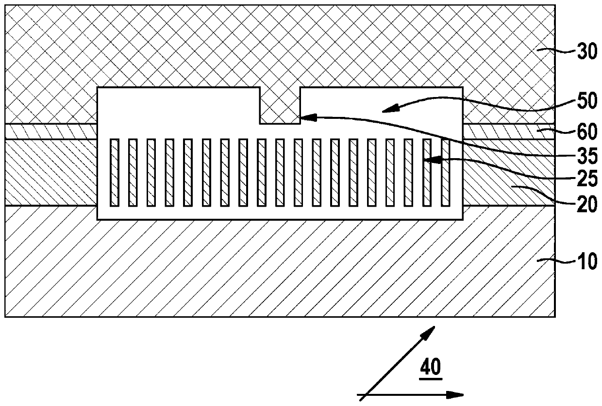
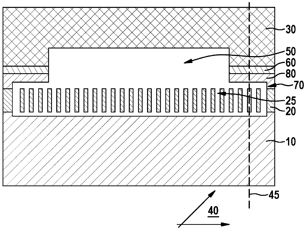
[0024] A schematic comparison of a prior art micromechanical device and a micromechanical device according to the invention with a covered bond frame is shown in cross section in FIGS. 1 and 2 .

[0025] FIG. 1 shows a prior art micromechanical device with a substrate, a micromechanical structure, a bond frame and a cover. Shown is a micromechanical device with a substrate 10 , a functional layer 20 and a cover 30 arranged one above the other parallel to the main plane of extent 40 . In this case, a cavity 50 is formed in the functional layer 20 , which cavity is surrounded by a bonding frame 60 . A micromechanical structure 25 is also formed in the functional layer 20 . The cover 30 is connected to the key frame 60 . The cover 30 has a cover stop 35 for delimiting the offset of the functional layer 20 perpendicular to the main plane of extent 40 .

[0026] figure 2 A micromechanical device according to the invention is shown with a substrate, a micromechanical structure, ...


PUM


Abstract

The invention relates to a micromechanical device, the micromechanical device having a substrate (10), a functional layer (20) and a cap (30), which are arranged one above another parallel to a main extension plane (40), wherein a cavity (50) is formed in the functional layer (20), said cavity being surrounded by a bond frame (60) extending parallel to the main extension plane (40), wherein the cap (30) is connected to the bond frame (60). The heart of the invention consists in the cavity (50) being arranged partly between bond frame (60) and substrate (10) in a direction (45) perpendicular tothe main extension plane (40). The invention also relates to a method for producing a micromechanical device.

Description

technical field [0001] The invention relates to a micromechanical device with a substrate, a functional layer and a cover arranged one above the other parallel to a main extension plane, wherein a cavity is formed in the functional layer, which cavity is surrounded by a bond frame, the bond The frame runs parallel to the main plane of extent, the cover being connected to the key frame. Background technique [0002] MEMS components require an encapsulation for shielding sensitive measurement structures against undesired environmental influences, such as particles, moisture. According to the prior art, the connection of the cap to the MEMS element (sensor) takes place via bonded connections. Typical methods are hermetic glass bonding and eutectic bonding. However, other bonding methods for this connection are also used. [0003] Common to all bonding methods is that a region must remain free around the sensor in which the bonding connection between the cap and the MEMS elem...

Claims


Application Information

Patent Timeline
Patent Type & Authority Applications(China)
IPC IPC(8): B81B7/00B81B3/00
CPCB81B3/0051B81B7/0077B81B7/0032B81B7/02B81B2201/02B81B2203/0315B81C1/00B81C2203/0109
Inventor J·赖因穆特M·兰巴赫
Owner ROBERT BOSCH GMBH
Learn More