A tight sandstone pressure gradient testing device

A compact sandstone and pressure gradient technology, applied in the direction of measuring devices, applying stable tension/pressure to test material strength, strength characteristics, etc., can solve the problem of lack of direct cleaning of gravel, increase the workload of users, and the influence of fixed sleeves is relatively large. Major problems, to achieve the effect of reducing adverse effects, improving convenience and reliability, and improving test accuracy

Active Publication Date: 2022-06-28
XI'AN PETROLEUM UNIVERSITY
View PDF8 Cites 0 Cited by
  • Summary
  • Abstract
  • Description
  • Claims
  • Application Information

AI Technical Summary

Problems solved by technology

[0002] For industries such as geological exploration and mineral mining, the research on tight sandstone is very important, especially the pressure performance of tight sandstone, which can provide guidance data and basis for geology, geological minerals, etc., because the pressure test device When testing sandstone, it is necessary to continuously pressurize to test the maximum pressure that the sandstone can withstand, and when the critical point of sandstone pressure is reached, the sandstone will be crushed and scattered around, and the current testing device lacks a pair of broken pieces. The direct cleaning of stones usually requires the user to manually clean up the workload of the user, and there is a lack of certain protective measures to prevent the flying gravel from causing harm to the user. Moreover, during the pressure test, it is necessary to The sandstone is fixed and clamped. The current clamping method generally adopts rigid clamping, that is, a clamping sleeve is set, and then the fixed sleeve is set on the outer periphery of the sandstone. This method of surface contact clamping is in the pressure test. The influence of sandstone is greater, which makes the pressure detection inaccurate and affects the detection effect

Method used


Image

  • A tight sandstone pressure gradient testing device
  • A tight sandstone pressure gradient testing device
  • A tight sandstone pressure gradient testing device

Examples


Embodiment Construction

[0024] The following will be combined with the Figure 1-7 The present invention is described in detail, and the technical solutions in the embodiments of the present invention are clearly and completely described. Obviously, the described embodiments are only a part of the embodiments of the present invention, rather than all the embodiments. Based on the embodiments of the present invention, all other embodiments obtained by those of ordinary skill in the art without creative efforts shall fall within the protection scope of the present invention.

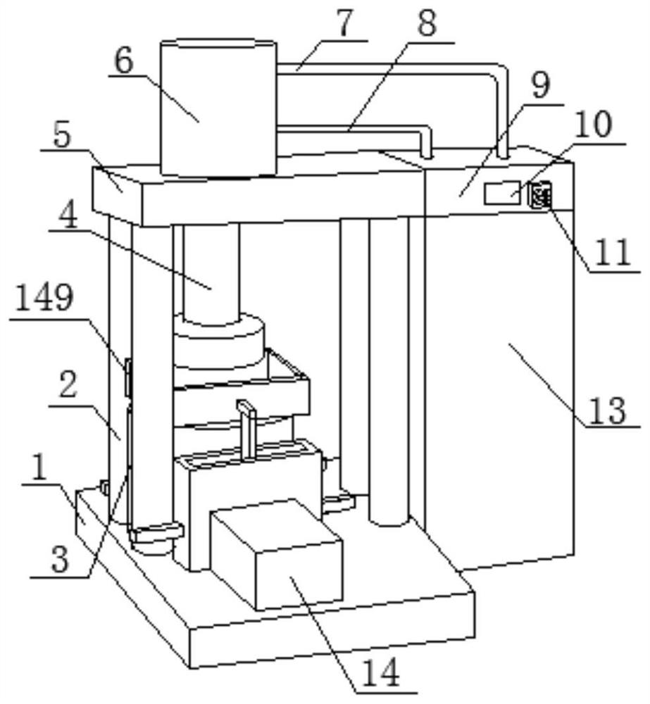
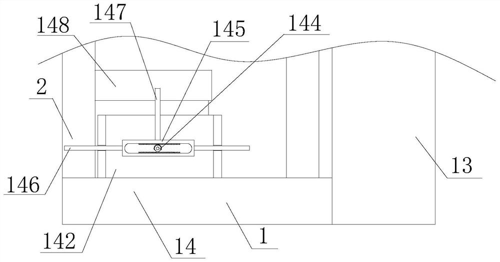
[0025] The present invention provides a compact sandstone pressure gradient test device, comprising a support plate 1, a fixed pressure plate 3 and a pressing mechanism. The upper end of the supporting plate 1 is welded and fixed to a support rod 2, and the top of the support rod is provided with the pressing mechanism. , the support plate is provided with the fixed pressure plate, and the pressing mechanism can move toward the f...


PUM


Abstract

The invention discloses a dense sandstone pressure gradient testing device, which comprises an anti-sputtering and cleaning mechanism and a dense sandstone clamping mechanism. The anti-sputtering and cleaning mechanism is arranged around the fixed pressure plate so as to facilitate the Protect the sandstone to be tested and clean the tested sandstone. The tight sandstone clamping mechanism can clamp and fix the cylindrical tight sandstone along its radial direction from the outer peripheral surface of the cylindrical tight sandstone. Its clamping area is small, and The clamping position basically achieves point contact or very small surface contact, which reduces the adverse effect on sandstone during down-press testing and improves test accuracy. At the same time, each clamping assembly on each fixed sleeve of the present invention is synchronously controlled Clamping is simple and convenient, effectively improves the convenience and reliability of clamping, improves the clamping effect, and facilitates the adjustment of the clamping mechanism of the dense sandstone according to the length of the sandstone and other factors to improve the applicability.

Description

technical field [0001] The invention specifically relates to a tight sandstone pressure gradient testing device, which relates to the related field of pressure testing. Background technique [0002] For geological exploration, mining and other industries, the study of tight sandstone is very important, especially the pressure performance of tight sandstone, which can provide good guidance data and basis for geology, geology and mining, etc. When testing sandstone, it is necessary to continuously pressurize to test the maximum pressure that the sandstone can withstand. When the critical point of sandstone pressure is reached, the sandstone will be crushed and scattered, and the current test device lacks the ability to crush the sandstone. The direct cleaning of the stone usually requires the user to perform manual cleaning, which increases the workload of the user, and lacks certain protective measures to prevent the scattered gravel from causing damage to the user. Moreover,...

Claims


Application Information

Patent Timeline
Patent Type & Authority Patents(China)
IPC IPC(8): G01N3/08G01N3/04B08B1/00
CPCG01N3/08G01N3/04B08B1/00G01N2203/0676
Inventor 陈朝兵牛小兵周创飞陈新晶张浩
Owner XI'AN PETROLEUM UNIVERSITY
Why Eureka
Try Eureka