Stirring tank for wet cement production

A mixing tank and wet method technology, which is applied in the field of cement wet production mixing tank, can solve the problems of reducing the internal volume of the mixing tank, insufficient mixing, and different mixing degrees of slurry, so as to avoid slurry residue and improve uniformity Effect

Inactive Publication Date: 2020-06-26
王柏彰
View PDF0 Cites 6 Cited by
  • Summary
  • Abstract
  • Description
  • Claims
  • Application Information

AI Technical Summary

Problems solved by technology

[0004] The invention provides a mixing tank for cement wet production, aiming to solve the following problems in the mixing and homogenization process in the current wet cement production process: (1) the stirring blade is driven by the stirring shaft located in the center of the tank body to When the slurry is homogenized, due to the different linear speeds on the stirring blades, the stirring degree of the slurry is also different. The stirring degree of the slurry closer to the stirring shaft is lower than that of the farther away from the stirring shaft. , resulting in uneven stirring; (2) due to the large viscosity of the slurry, it is easy to adhere to the inner wall of the mixing tank during the discharge process, and becomes a solid attached to the inner wall after hardening, reducing the internal volume of the mixing tank. It will also cause the center of gravity of the mixing tank to shift

Method used


Image

  • Stirring tank for wet cement production
  • Stirring tank for wet cement production
  • Stirring tank for wet cement production

Examples


Embodiment Construction

[0031] The embodiments of the present invention will be described in detail below with reference to the accompanying drawings, but the present invention can be implemented in many different ways defined and covered by the claims.

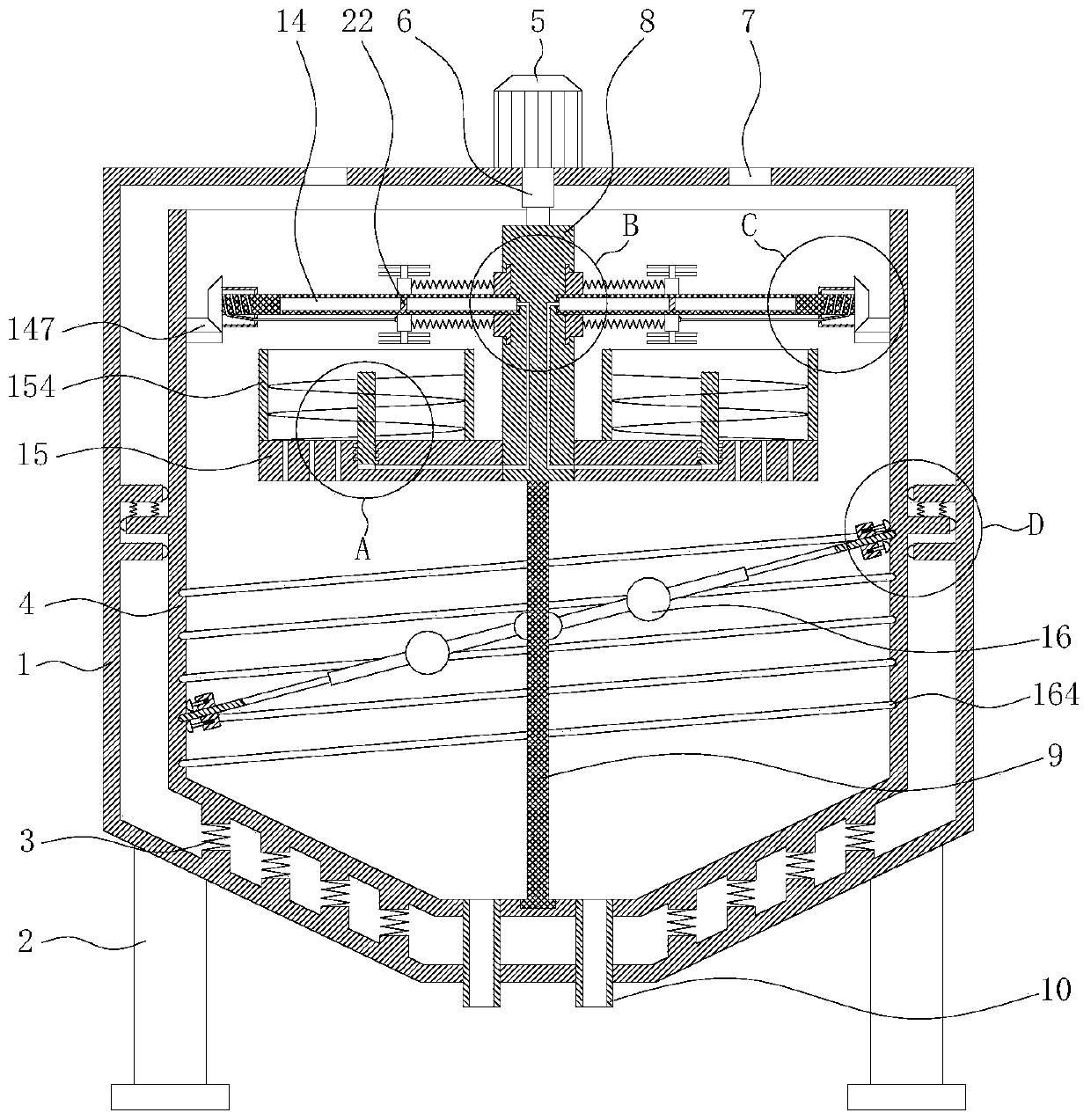
[0032] Such as Figure 1-Figure 7 As shown, this embodiment provides a mixing tank for cement wet production, which includes a vertical cylindrical outer tank body 1, the bottom plate of the outer tank body 1 is conical in a downwardly recessed shape, and a support is installed vertically below it. leg 2. The top of the outer tank body 1 bottom plate is vertically fixedly installed with a first spring 3 by a spring seat, and the top of the first spring 3 is fixedly installed with an inner tank body 4 coaxial with the outer tank body 1, and the inner tank body 4 top openings. Relative movement in the vertical direction can be generated between the inner tank body 4 and the outer tank body 1 .

[0033] The top of the outer tank body 1 top plate is v...


PUM


Abstract

The invention belongs to the technical field of cement production, and particularly relates to a stirring tank for cement wet production. The stirring tank comprises an outer tank body and an inner tank body; a reciprocating motor is mounted on a top plate of the outer tank body and is connected with a telescopic shaft; a square column is mounted at the bottom of the telescopic shaft, and a rotating shaft is mounted at the bottom of the square column; an upper baffle ring and a lower baffle ring are mounted on the inner side wall of the outer tank body; a limiting ring is mounted on the outerside wall of the inner tank body; and a stirring mechanism and a conveying mechanism are mounted on the square column, and a scraping mechanism is mounted on the rotating shaft. The stirring uniformity can be improved when slurry is stirred and homogenized, and the slurry is prevented from being attached to the inner side wall of the inner tank body in the discharging process.

Description

technical field [0001] The invention belongs to the technical field of cement production, and in particular relates to a mixing tank for cement wet production. Background technique [0002] Cement is a powdery hydraulic inorganic gelling material. It can be mixed with water to form a slurry, which can be hardened in air or in water, and can firmly bind sand, stone and other materials together. As an important cementitious material, cement is widely used in civil engineering, cement and national defense projects. According to different production processes, cement production can be divided into dry production and wet production; the wet production process is to mix cement raw materials, add water and wet powder to grind into slurry, and then send the slurry into the mixing tank through The stirring shaft located in the center of the tank drives the stirring blades to homogenize the slurry, and then it is dried and calcined. In the current wet production process, there are t...

Claims


Application Information

Patent Timeline
Patent Type & Authority Applications(China)
IPC IPC(8): B01F11/00B01F15/00
CPCB01F31/40B01F35/12B01F35/00B01F35/123B01F2101/28
Inventor 王柏彰苏刚
Owner 王柏彰
Why Eureka
Try Eureka