Powder collecting system

A collection system and powder technology, applied in the direction of solid separation, magnetic separation, measuring devices, etc., can solve the problems of single and frequent air flow channels, powder blockage, etc., to extend the service life, improve production efficiency, and reduce inner cavity blockage The effect of probability

Pending Publication Date: 2020-06-26
XIA TAI XIN SEMICON QING DAO LTD
View PDF0 Cites 0 Cited by
  • Summary
  • Abstract
  • Description
  • Claims
  • Application Information

AI Technical Summary

Problems solved by technology

The air flow channel in the existing powder capture device is single, which is easy to cause powder blockage, and the equipment cannot send prompt information in time when the powder is blocked, resulting in the need for engineers to clean the powder capture device frequently and regularly, making the service life of the powder capture device short. Reduced productivity of semiconductor manufacturing processes

Method used


Image

  • Powder collecting system
  • Powder collecting system
  • Powder collecting system

Examples


no. 1 example

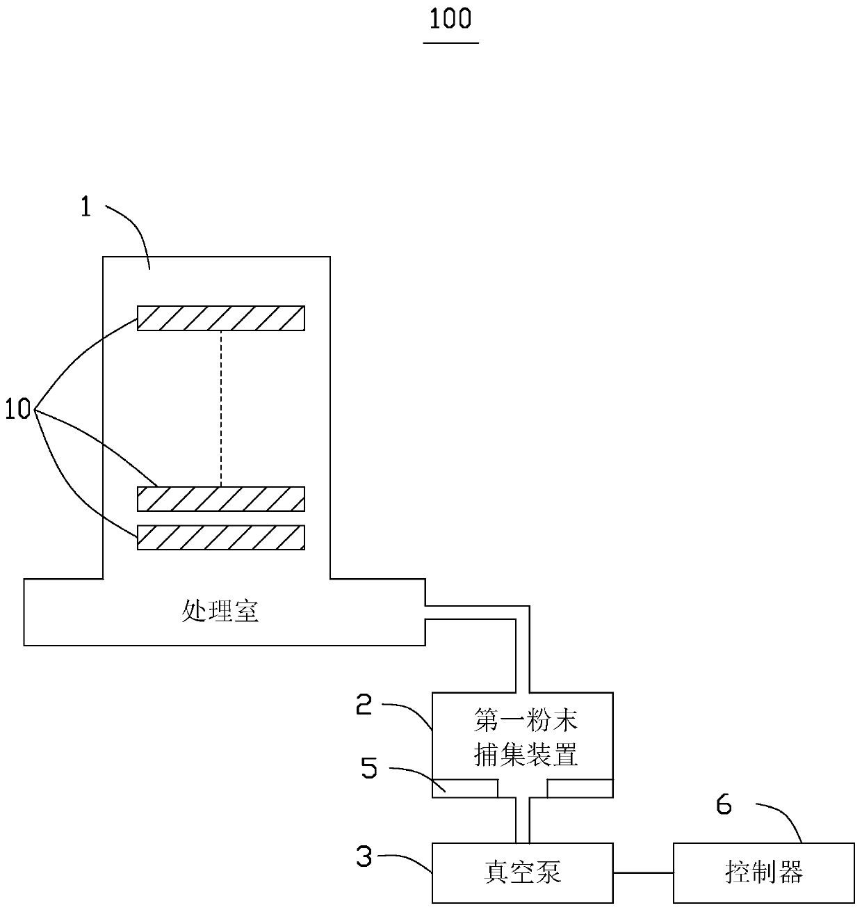
[0029] see figure 1 and figure 2 , In one embodiment, the powder collection system 100 includes a processing chamber 1 , a first powder collection device 2 and a vacuum pump 3 . At least one semiconductor wafer 10 is placed in the processing chamber 1 , and the first powder collection device 2 is connected between the processing chamber 1 and the vacuum pump 3 .

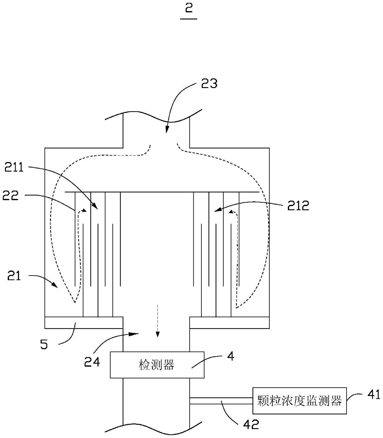
[0030] The first powder collecting device 2 includes an inner chamber 21 and a plurality of partitions 22, and the plurality of partitions 22 are arranged vertically and staggered in the inner chamber 21 for dividing the inner chamber into a plurality of mutually The communicating area forms a channel communicating with the air inlet end 23 and the air outlet end 24 of the inner chamber 21 . The channels include a first air flow channel 211 and a second air flow channel 212 arranged in parallel. The inlet port 23 of the inner cavity 21 communicates with the processing chamber 1 , and the gas outlet port 24 of the...

no. 2 example

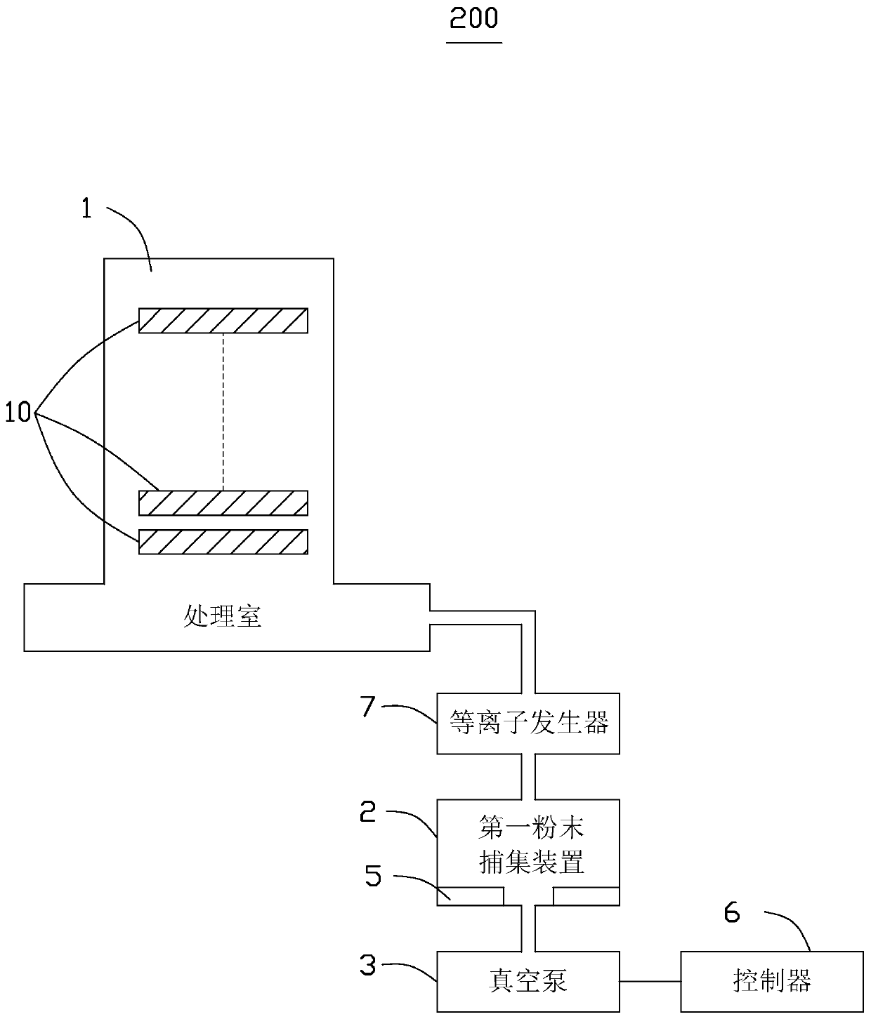
[0037] see image 3 , In the second embodiment, the powder collection system 200 includes a processing chamber 1 , a first powder collection device 2 and a vacuum pump 3 . At least one semiconductor wafer 10 is placed in the processing chamber 1 , and the first powder collection device 2 is connected between the processing chamber 1 and the vacuum pump 3 . The first powder collecting device 2 includes an inner chamber 21 and a plurality of partitions 22, and the plurality of partitions 22 are arranged vertically and staggered in the inner chamber 21 for dividing the inner chamber into a plurality of mutually The communicating area forms a channel communicating with the air inlet end 23 and the air outlet end 24 of the inner chamber 21 . The channels include a first air flow channel 211 and a second air flow channel 212 arranged in parallel. The inlet port 23 of the inner cavity 21 communicates with the processing chamber 1 , and the gas outlet port 24 of the inner cavity com...

no. 3 example

[0041] see Figure 5 , In the third embodiment, the powder collection system 300 includes a processing chamber 1 , a first powder collection device 2 and a vacuum pump 3 . At least one semiconductor wafer 10 is placed in the processing chamber 1 , and the first powder collection device 2 is connected between the processing chamber 1 and the vacuum pump 3 . The first powder collecting device 2 includes an inner chamber 21 and a plurality of partitions 22, and the plurality of partitions 22 are arranged vertically and staggered in the inner chamber 21 for dividing the inner chamber into a plurality of mutually The communicating area forms a channel communicating with the air inlet end 23 and the air outlet end 24 of the inner chamber 21 . The channels include a first air flow channel 211 and a second air flow channel 212 arranged in parallel. The inlet port 23 of the inner cavity 21 communicates with the processing chamber 1 , and the gas outlet port 24 of the inner cavity com...


PUM


Abstract

The invention provides a powder collecting system which comprises a processing chamber, a first powder capturing device and a vacuum pump. The first powder capturing device is communicated with the processing chamber. The vacuum pump is communicated with the powder capturing device. The first powder capturing device comprises an inner chamber and a plurality of baffle plates. The plurality of baffle plates are vertically arranged in the inner chamber in a staggered manner and are used for dividing the inner chamber into a plurality of intercommunicated areas, thereby forming channels which arecommunicated with the air inlet end and the air outlet end of the inner chamber. The channels comprise a first air channel and a second air channel which are arranged in parallel. The air inlet end of the inner chamber is communicated with the processing chamber. The air outlet end of the inner chamber is communicated with the vacuum pump. The powder collecting system further comprises a detector, and an air outlet end arranged in the inner chamber for detecting air current magnitude and furthermore determining whether cleaning of the first powder capturing device is required according to a detecting result.

Description

technical field [0001] The invention relates to the field of semiconductor equipment, in particular to a powder collection system. Background technique [0002] The semiconductor process includes depositing a thin film on the surface of a semiconductor wafer using Tetra-Ethyl-Ortho-Silicate (TEOS) as a material, and etching circuits on the surface of the semiconductor wafer by Chemical Vapor Deposition (CVD) . These process steps generate impurity powders, and particle contamination is a major concern when processing equipment processes semiconductor wafers. In order to avoid pollution caused by the circulation of impurity powder in the reaction chamber, it is usually necessary to install a powder capture device outside the gas outlet of the semiconductor process chamber. The air flow channel in the existing powder capture device is single, which is easy to cause powder blockage, and the equipment cannot send prompt information in time when the powder is blocked, resulting...

Claims


Application Information

Patent Timeline
Patent Type & Authority Applications(China)
IPC IPC(8): B03C1/30G01N15/06
CPCB03C1/30G01N15/06
Inventor 李东根李殷廷崔致久金成基
Owner XIA TAI XIN SEMICON QING DAO LTD
Why Eureka
Try Eureka