Self-cleaning type printing ink spraying gun head

A self-cleaning and ink technology, applied in the direction of spraying devices, liquid spraying devices, etc., can solve the problems of clogging the muzzle, clogging of the gun head, insufficient ink pressure, etc., to avoid clogging of the muzzle, ensure the effect of the ink, and increase the spraying pressure Effect

Active Publication Date: 2020-06-26
山东蓝彩天下教育科技有限公司
View PDF6 Cites 2 Cited by
  • Summary
  • Abstract
  • Description
  • Claims
  • Application Information

AI Technical Summary

Problems solved by technology

[0002] In order to solve the defects of fixed waste, exhaust gas and wastewater discharge in the traditional electroplating operation method, serious pollution and poor environmental protection effect; and limited processing, it must rely on large-scale equipment, high cost and complicated operation; the existing The technology is gradually adopting the spraying method to process the mirror surface, that is, the ink is evenly sprayed on the surface of the workpiece through the spray gun; in order to effectively ensure the quality of ink spraying, the structural design of the spray gun is particularly important
[0003] However, the existing ink spray gun head mainly exists in the process of use: a: the ink pressure inside the ink gun is not enough when spraying, causing the ink to scatter on the workpiece, which affects the quality of workpiece spraying; b: ink gun If the interior is not cleaned for a long time, the ink will precipitate and cause the gun head to be blocked, which will affect the uniformity of the ink on the ink gun; c: After the gun head of the ink gun is sprayed, there will be a large amount of ink remaining at the muzzle position. After each use, you need to Personnel clean and wipe in time, otherwise the muzzle will be blocked

Method used


Image

  • Self-cleaning type printing ink spraying gun head
  • Self-cleaning type printing ink spraying gun head
  • Self-cleaning type printing ink spraying gun head

Examples


Embodiment Construction

[0021] Embodiments of the present invention will be described below with reference to the drawings. In the process, in order to ensure the clarity and convenience of illustration, we may exaggerate the width of the lines or the size of the constituent elements in the diagram.

[0022] In addition, the following terms are defined based on the functions in the present invention, and may be different according to the user's or operator's intention or practice. Therefore, these terms are defined based on the entire content of this specification.

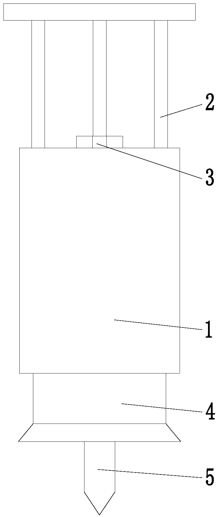
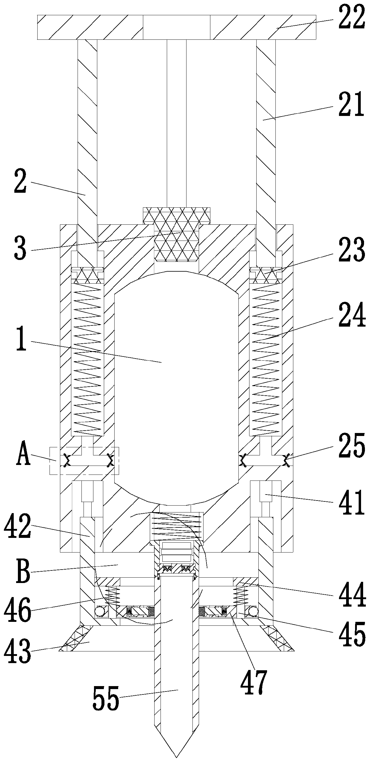
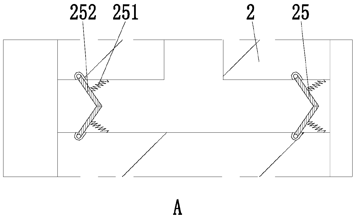
[0023] Such as Figure 1 to Figure 4 As shown, a self-cleaning ink spray gun head includes a gun barrel 1, a pressing unit 2, a rubber stopper 3, an auxiliary unit 4 and a gun head unit 5; the inside of the gun barrel 1 is a cavity structure, and the gun barrel The upper end of 1 is provided with an injection hole, and a rubber plug 3 is arranged on the injection hole to seal; At the hole, the auxiliary unit 4 is arranged on the outer...


PUM


Abstract

The invention provides a self-cleaning type printing ink spraying gun head which comprises a gun barrel, a pressing unit, a rubber stopper, an auxiliary unit and a gun head unit. The self-cleaning type printing ink spraying gun head can solve the main problems in the use process of an existing printing oil spraying gun head. The problems include that a, the pressure of printing ink is not large enough when the printing ink in the printing ink gun is sprayed, consequently the printing ink is scattered on a workpiece, and the spraying quality of the workpiece is affected; b, the interior of theprinting ink gun is not cleaned for a long time, consequently, the printing ink precipitates, a gun head is blocked, and the uniformity of the printing ink at the spraying position of the printing inkgun is affected; and c, after spraying use of the gun head of the printing oil gun, a large amount of printing ink is left at the position of a gun opening of the printing ink gun, after the printingink gun is used each time, people need to conduct cleaning and wiping in time, or the gun opening is blocked.

Description

technical field [0001] The invention relates to the technical field of spraying devices, in particular to a self-cleaning ink spray gun head. Background technique [0002] In order to solve the defects of fixed waste, exhaust gas and wastewater discharge in the traditional electroplating operation method, serious pollution and poor environmental protection effect; and limited processing, it must rely on large-scale equipment, high cost and complicated operation; the existing The technology is gradually adopting the method of spraying to process the mirror surface, that is, the ink is evenly sprayed on the surface of the workpiece through the spray gun; in order to effectively ensure the quality of ink spraying, the structural design of the spray gun is particularly important. [0003] However, the existing ink spray gun head mainly exists in the process of use: a: the ink pressure inside the ink gun is not enough when spraying, causing the ink to scatter on the workpiece, wh...

Claims


Application Information

Patent Timeline
Patent Type & Authority Applications(China)
IPC IPC(8): B05B9/04B05B15/50B05B15/25
CPCB05B9/04B05B15/25B05B15/50
Inventor 王鑫杰金双
Owner 山东蓝彩天下教育科技有限公司
Why Eureka
Try Eureka