
Grinding machine for mechanical and electrical equipment parts

A technology for electromechanical equipment and spare parts, which is applied in the field of electromechanical equipment spare parts grinding machines, can solve the problems of troublesome replacement of grinding pieces, waste of time, and increase of manual labor, so as to avoid insufficient grinding, save replacement time, and improve work. The effect of efficiency

Inactive Publication Date: 2020-06-26
徐焕东
View PDF17 Cites 1 Cited by
  • Summary
  • Abstract
  • Description
  • Claims
  • Application Information

AI Technical Summary

Problems solved by technology

The grinding machine may encounter tiny dead angles when grinding the surface of different parts, which will cause the machine to need to replace the grinding sheet for grinding, resulting in an increase in manual labor and a waste of time, and it is more troublesome to replace the grinding sheet

Method used


Image

  • Grinding machine for mechanical and electrical equipment parts
  • Grinding machine for mechanical and electrical equipment parts
  • Grinding machine for mechanical and electrical equipment parts

Examples


Embodiment 1

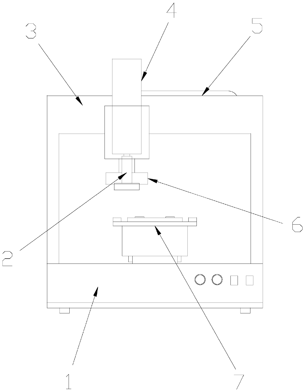
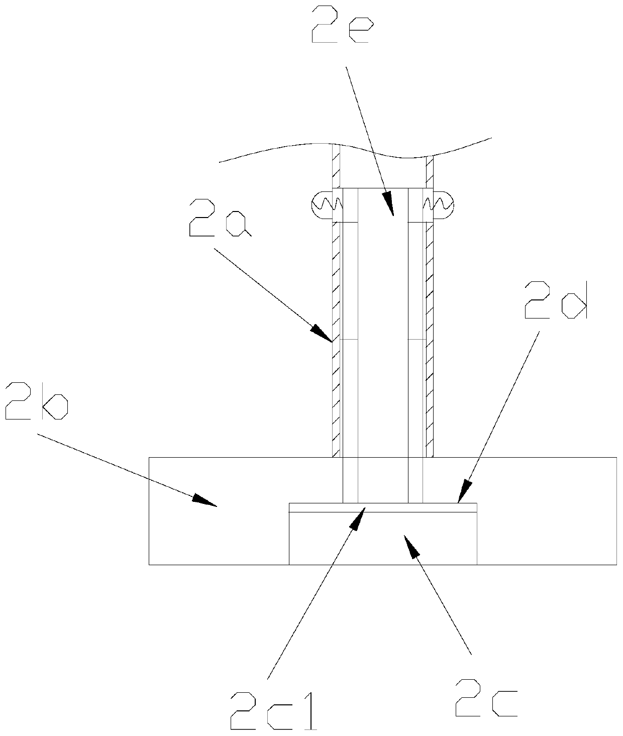
[0028] see Figure 1-Figure 4 , the present invention provides a grinding machine for spare parts of electromechanical equipment, the structure of which includes a base 1, a biaxial grinding mechanism 2, a rail frame 3, a driving device 4, a drag chain 5, a dust suppression mechanism 6, and a workbench 7. The top of the base 1 is provided with a guide rail frame 3, the base 1 and the guide rail frame 3 are mechanically connected, the middle position of the top of the base 1 is provided with a workbench 7, and the base 1 and the workbench 7 connected, the front end of the guide rail frame 3 is provided with a drive device 4, the guide rail frame 3 and the drive device 4 are connected by a drag chain 5, and the bottom end of the drive device 4 is provided with a dust suppression mechanism 6, The driving device 4 is movably connected with the dust suppression mechanism 6 , and the inner side of the dust suppression mechanism 6 is provided with a biaxial grinding mechanism 2 , and...

Embodiment 2

[0036] see Figure 1-Figure 6 , the present invention provides a grinding machine for spare parts of electromechanical equipment. The dust suppression mechanism 6 is composed of a fixed cylinder 6a, a negative pressure worm wheel 6b, a linkage ring 6c, a second sliding ball 6d, and a dust collection box 6e. The fixed A negative pressure worm gear 6b ​​is provided on the inner side of the cylinder 6a. The fixed cylinder 6a and the negative pressure worm gear 6b ​​are slidably matched through the second sliding ball 6d. A linkage ring 6c is provided in the middle of the negative pressure worm gear 6b. The negative pressure worm gear 6b ​​is fixedly connected with the linkage ring 6c, and three dust collecting boxes 6e are equidistantly arranged on the surface of the fixed cylinder 6a.

[0037] The inner side of the fixed cylinder 6a is provided with dust-shielding blades 6a1, and the fixed cylinder 6a is fixedly connected with the dust-shielding blades 6a1.

[0038] The dust co...


PUM


Abstract

The invention discloses a grinding machine for mechanical and electrical equipment parts. The grinding machine structurally comprises a base, a double-shaft grinding mechanism, a guide rail frame, a driving device, a drag chain, a dust suppression mechanism and a workbench, and the double-shaft grinding mechanism is composed of a power shaft, a concave grinding disc, a small grinding sheet, an adhesive groove and a telescopic linkage rod. According to the grinding machine, the double-shaft grinding mechanism is utilized to achieved two kinds of grinding effects, the surface of a workpiece is grinded through the concave grinding disc, an dead angle on the surface of the workpiece is subjected to secondary grinding by using the small grinding sheet, the incomplete grinding of the workpiece is avoided, the working efficiency is improved, the labor volume is reduced, the replacing time of the grinding sheet is saved, a linkage ring is driven by the power shaft to rotate, thus when a negative pressure worm gear rotates, negative pressure wind force can be generated, scraps or dust on the surface of the workpiece is absorbed upwards, interrupting, filtering and collecting are conducted through a dust collection box, the harm of dust to the respiratory tracts of workers is avoided, and the explosion of friction between dust can further be avoided.

Description

technical field [0001] The invention relates to the field of grinders, in particular to a grinder for spare parts of electromechanical equipment. Background technique [0002] With the improvement of people's living standards, people consume more and more cars, and the market for auto parts is getting bigger and bigger. In recent years, auto parts manufacturers are also developing rapidly. Parts after initial production have very fine microscopic metal particles on the surface, known as burrs, which are formed during cutting, grinding, milling and other similar chipping processes. [0003] In the process of grinding the surface of spare parts, dust will be generated, which is particularly harmful to the respiratory tract of workers, and some material dust flying out is also explosive and dangerous. The grinding machine may encounter small dead angles when grinding the surface of different parts, which will cause the machine to need to replace the grinding sheet for grindin...

Claims


Application Information

Patent Timeline
Patent Type & Authority Applications(China)
IPC IPC(8): B24B19/00B24B27/00B24B55/06B24B41/02B24B41/00
CPCB24B19/00B24B27/0046B24B41/007B24B41/02B24B55/06
Inventor 徐焕东
Owner 徐焕东
Learn More