
Eureka
For R&D, Eureka makes reading and utilizing patents & technical documents easy.
Eureka AIR
Designed for self-driven R&D workflows. Generate viable solutions, solve complex R&D challenges, empower your innovation with AI.

Eureka Materials
Designed for material experts only. Revolutionize your material R&D, from search, analyze, to developing new materials.

TechResearch
Generate reliable direction feasibility study reports for your R&D in just a few steps.

TechSeek
Discover and master advanced knowledge NOW. Basics, ideas, possibilities, all at once.

TechMind
As an expert in R&D Theories, TechMind can generates customized viable solutions instantly.

TechRisk
Analyze your overall solution with one click, know your potential R&D risks in advance.

TechMonitor
Get weekly tech updates, stay abreast of the latest tech innovations and key insights.
Cutting device for adhesive sticker production
A cutting and cutting technology, which is applied in the field of self-adhesive, can solve the problems of not being able to collect waste, not being able to fix the self-adhesive, and not being able to meet market demand, so as to achieve the effect of improving practicability, cutting efficiency and quality
- Summary
- Abstract
- Description
- Claims
- Application Information
AI Technical Summary
Problems solved by technology
Method used
Image

Examples
Embodiment 1
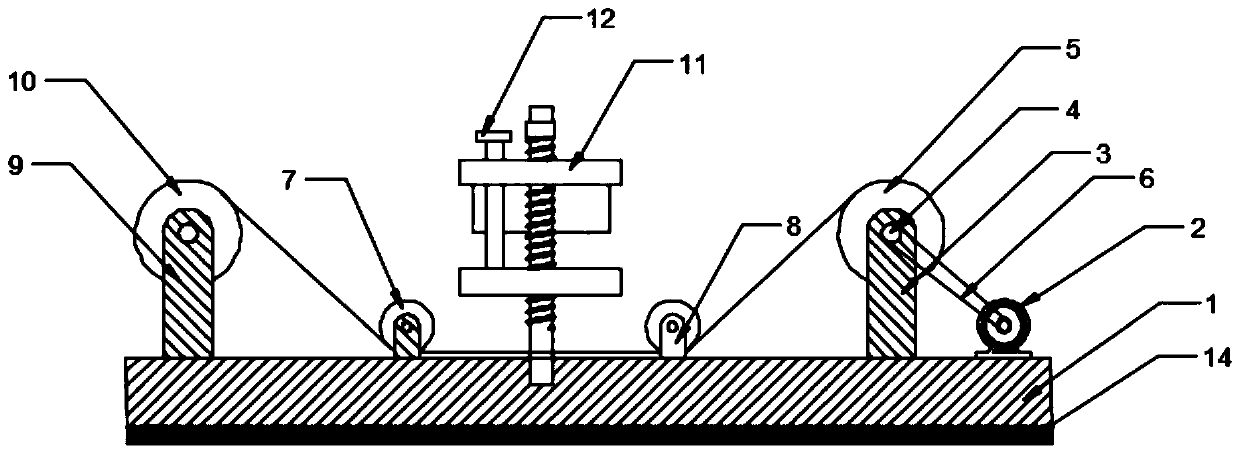
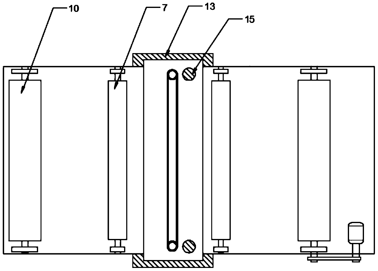
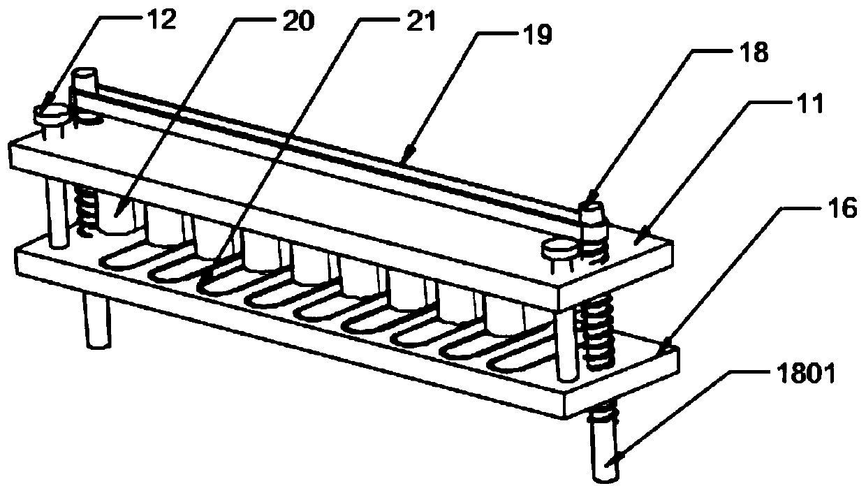
[0024] see Figure 1-4 , a cutting device for self-adhesive production, including a bottom plate 1, a self-adhesive discharging assembly and a waste collection assembly are respectively arranged at both ends of the bottom plate 1, and a Cutting assembly, the specific type of the cutting assembly is not limited. In this embodiment, preferably, the cutting assembly includes a lifting plate 11, a block 12, a guide rail 13, a fixed rod 15, a pressing plate 16, a screw rod 18, a linkage Belt 19, cutting knife upper die 20 and slitting lower die 22, guide rail 13 are fixedly installed on both sides of base plate 1, and the two ends of lifting plate 11 and pressing plate 16 are movably installed in guide rail 13 and are threadedly connected with screw mandrel 18. The screw rods 18 are arranged symmetrically on both sides of the bottom plate 1, and the lower end is rotatably installed in the bottom plate 1. A vertically placed fixed rod 15 is installed on the pressure plate 16. The up...
Embodiment 2
[0033] In order to improve the cutting effect, this embodiment is further improved on the basis of Embodiment 1. The improvement is that: limit components are arranged on both sides of the cutting component, and the specific type of the limit component is not limited. This embodiment Among them, preferably, the limit assembly includes a limit roller 7 and a support frame 8, the support frame 8 is fixedly installed on both sides of the bottom plate 1, the limit roller 7 is rotatably installed between the support frames 8, and the bottom end of the limit roller 7 Close to the bottom plate 1, by setting two limit components, the self-adhesive raw materials during cutting can be attached to the bottom plate 1 in parallel, so as to improve the cutting quality.
[0034] To sum up, the pressure plate 16 is used to fix the self-adhesive, and then the upper die 20 of the cutter and the lower die 22 are used to complete the cutting, which greatly improves the cutting efficiency and quali...
PUM
 Abstract
Description
Claims
Application Information
 - R&D Engineer
- R&D Manager
- IP Professional
- Industry Leading Data Capabilities
- Powerful AI technology
- Patent DNA Extraction
Browse by: Latest US Patents, China's latest patents, Technical Efficacy Thesaurus, Application Domain, Technology Topic, Popular Technical Reports.
© 2024 PatSnap. All rights reserved.Legal|Privacy policy|Modern Slavery Act Transparency Statement|Sitemap|About US| Contact US: help@patsnap.com