Movable shunting blocking system for debris flow prevention and control

A mud-rock flow and mobile technology, which is applied in dikes, water conservancy projects, sea area engineering, etc., can solve the problems of unsatisfactory mud-rock flow effects, achieve strong anti-geological disaster ability, reduce impact force and destructiveness, and reduce contact area.

Pending Publication Date: 2020-06-26
段刚强
View PDF8 Cites 6 Cited by
  • Summary
  • Abstract
  • Description
  • Claims
  • Application Information

AI Technical Summary

Benefits of technology

This patented technology describes various technical features for creating an effective and reliable way to prevent damage caused from heavy objects or other sources during transport operations without causing significant negative consequences like environmental pollution. It uses multiple layers of materials called diodes and trivalve structures to absorb shock waves while allowing them to separate before being stopped. A slurry accumulation region prevents further movement of degradants and reduces their impact upon surrounding areas. Different types of blocks made of different material may include tungsten carbons, tantum cars, zinc diode bars, rubble shieldings, and ballistic resistant systems. Overall, this innovative design helps improve safety measures against threatening events involving high levels of force and potential harmful environments.

Problems solved by technology

Technological Problem: Debris Flow (DF) describes an issue related to road safety during severe weather events like droughts or fires. DF can cause significant loss if there're no effective way to stop this phenomenon effectively without rebuilding these structures afterwards. Current solutions involve constructing temporary barriers around specific locations within roads/rail systems but they have limitations because their design may lead to poorly designed protection measures.

Method used


Image

  • Movable shunting blocking system for debris flow prevention and control
  • Movable shunting blocking system for debris flow prevention and control
  • Movable shunting blocking system for debris flow prevention and control

Examples


Embodiment 1

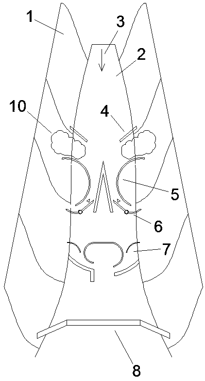
[0044] Such as figure 1 As shown, a movable diversion barrier system for debris flow prevention and control, the barrier system is set in the debris flow channel 2 formed between the highlands 1 on both sides, according to the flow direction 3 of the debris flow in the debris flow channel 2, the barrier system It includes a movable diverter dam, an energy dissipation retaining dam 7 and an intercepting dam 8 arranged in sequence, wherein the movable diverter dam includes a silting diversion dam 5 and two movable diversion mechanisms 6, and the silting diversion dam 5 Divide the debris flow into two strands, and then under the guidance of two movable diversion mechanisms 6, carry out secondary diversion and stop silting on the divided debris flow; the energy dissipation retaining dam 7 divides the debris flow into two strands after blocking, and The two streams of debris flows diverted to form convective flows with intersecting flow directions, and then hedge to form turbulent ...

Embodiment 2

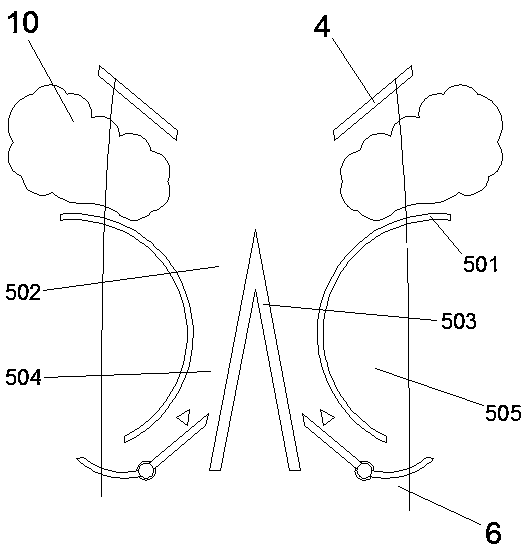
[0048] This embodiment is an improvement made on the basis of Embodiment 1, its basic structure is the same as that of Embodiment 1, and the improvements are as follows: Figure 2-4 As shown, the silting stop and diversion dam 5 includes first arc-shaped dam bodies 501 symmetrically arranged on both sides of the debris flow channel 2, and the upstream ends of the two first arc-shaped dam bodies 501 cross the two ends of the debris flow channel 2 respectively. The sides are connected to the highlands 1 on both sides, and there is a gap between the downstream end and the two sides of the debris flow channel 2, so that the backwater surface of the two first arc-shaped dam bodies 501 cooperates with the highlands 1 on both sides to form a direction facing downstream. The first silting zone 505 of the opening; a hyperbolic drainage channel 502 is formed between the two first arc-shaped dam bodies 501, and a triangular diversion dam 503 is arranged in the drainage channel 502, and th...

Embodiment 3

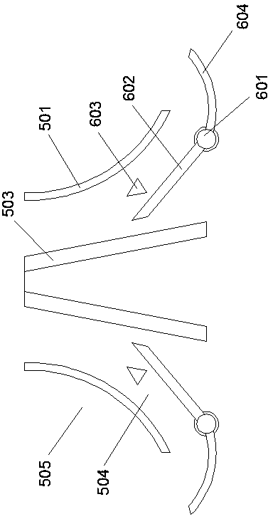
[0053] This embodiment is an improvement made on the basis of Embodiment 2, its basic structure is the same as that of Embodiment 2, and the improvements are as follows: Figure 2-4 As shown in and 6-7, the side of the first diversion plate 602 facing the first arc-shaped dam body 501 on this side is provided with a limit pile 603 to limit its deflection to the side of the diversion dam 503, and the limit pile 603 is triangular cement pile, and one of the sharp corners of its triangle faces the direction of the debris flow. The bottoms of the first diversion plate 602 and the second diversion plate 604 are provided with several support columns along their length direction, and the bottom end of each support column has a spherical support body 605 supported on the ground; the spherical support body 605 is actually On the top is a sphere supported by cement concrete, so that the contact area with the ground is small, and it can be rotated conveniently when impacted by debris flo...


PUM


Abstract

The invention relates to a movable shunting blocking system for debris flow prevention and control. The blocking system comprises a desilting shunting dam, two movable flow guiding mechanisms, an energy dissipation blocking dam and an intercepting dam; and the debris flow is divided into two strands by the desilting shunting dam and then is subjected to secondary shunting and desilting under the guidance of the movable flow guiding mechanisms, the energy dissipation blocking dam is used for dividing the debris flow into two strands, guiding the two strands of debris flow to form convection currents which flow to the intersecting direction, and then turbulent flow is formed through hedging during intersection so as to dissipate the energy of the debris flow. According to movable shunting blocking system for debris flow prevention and control in the invention, a multi-level and multi-functional elastic prevention and control mechanism composed of the movable shunting dam, the energy dissipation blocking dam and the intercepting dam is established in a flow channel where the debris flow happens frequently to carry out elastic interception, partial interception, region retention and deceleration energy dissipation on the debris flow, so that the impact force and the damage property of the debris flow are greatly reduced; and the blocking system is high in anti-geological disaster capability, and even if part of damage occurs, the prevention and treatment effect is not seriously affected.

Description


Claims


Application Information

Patent Timeline
Owner 段刚强
Why Eureka
Try Eureka