
Machining method of multi-angle tiny square groove

A processing method and a technology of square slots, which are applied in the direction of electrical components, printed circuit manufacturing, printed circuits, etc., can solve problems affecting product quality, cannot be added to the lower hole, and move left and right, so as to improve processing quality, simplify processing, and avoid bump effect

Inactive Publication Date: 2020-06-26
JIANGSU SUHANG ELECTRONIC CO LTD
View PDF3 Cites 1 Cited by
  • Summary
  • Abstract
  • Description
  • Claims
  • Application Information

AI Technical Summary

Problems solved by technology

[0002] When the traditional PCB board processes tiny square slots, a round hole that is one specification larger than the gong knife will be added to one corner of the tiny square slot as the lower hole. For tiny square slots whose length and width are slightly larger than the diameter of the gong knife, for example A 0.6mm gong knife cannot be added to the lower hole in the shape of a small square groove with a length and width of 0.7mm. Please refer to the attached image 3 , when the gong knife is lowered from a certain corner, because there is no hole for the lower knife, the gong knife will move left and right when it touches the PCB board (attached figure 1 For the tiny square grooves that require processing, attach figure 2 It is a small square groove actually processed), resulting in a state of bumps at a certain point after molding, which affects product quality

Method used


Image

  • Machining method of multi-angle tiny square groove
  • Machining method of multi-angle tiny square groove
  • Machining method of multi-angle tiny square groove

Examples


Embodiment Construction

[0020] A preferred embodiment of the present invention will be described in detail below in conjunction with the accompanying drawings.

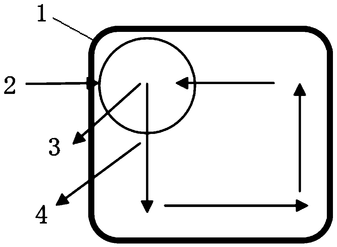
[0021] see Figure 4 , is the processing method of a kind of multi-angle tiny square groove of the present invention, takes the 0.6mm gong cutter to drill the tiny square groove that length and width are 0.7mm as an example, and comprises the following steps:

[0022] Step 1, drill a lower hole 2 with a radius of 0.65mm at the center of the tiny square groove 1;

[0023] Step 2, take the center of the lower knife hole 2 as the starting point, and move the gong knife of the gong groove along the radial direction of a side of the vertical tiny square groove of the lower knife hole to a side position of the tiny square groove (the tiny square groove in the figure the upper side of the square groove), and then move the gong knife clockwise or counterclockwise around the four sides of the tiny square groove for a week, and then return to the cen...


PUM


Abstract

The invention discloses a machining method of a multi-angle tiny square groove. The method comprises the following steps: a lower cutter hole of which the radius is smaller than the length and the width of a tiny square groove is formed by drilling in the central position of the tiny square groove; and then, with the center of the lower cutter hole as a starting point, a milling cutter of a milling groove performs milling to one side edge of the tiny square groove along the radius direction of one side edge, perpendicular to the tiny square groove, of the lower cutter hole, and the milling cutter surrounds the four side edges of the tiny square groove for a circle along the same direction, returns to the central position of the lower cutter hole and stops milling, so that the tiny square groove can be obtained. Due to the fact that the cutter stops milling in the center of the tiny square groove finally, salient points are avoided, and the machining quality is improved. Meanwhile, themachining method has the advantages of being easy and fast in machining, high in precision and the like.

Description

technical field [0001] The invention belongs to the technical field of PCB board processing, and in particular relates to a processing method for multi-angle tiny square grooves. Background technique [0002] When the traditional PCB board processes tiny square slots, a round hole that is one specification larger than the gong knife will be added to one corner of the tiny square slot as the lower hole. For tiny square slots whose length and width are slightly larger than the diameter of the gong knife, for example A 0.6mm gong knife cannot be added to the lower hole in the shape of a small square groove with a length and width of 0.7mm. Please refer to the attached image 3 , when the gong knife is lowered from a certain corner, because there is no hole for the lower knife, the gong knife will move left and right when it touches the PCB board (attached figure 1 For the tiny square grooves that require processing, attach figure 2 It is a small square groove actually proces...

Claims


Application Information

Patent Timeline
IPC IPC(8): H05K3/00
CPCH05K3/0044
Inventor 倪蕴之朱永乐孙思雨
Owner JIANGSU SUHANG ELECTRONIC CO LTD
Learn More